Medical Treatment System and Method

a treatment system and treatment method technology, applied in the field of medical treatment system and method, can solve the problems of collateral tissue damage, inability to accurately aim the beam, and difficulty in providing accurate positional information in order to correct aim the beam,

Inactive Publication Date: 2007-03-08
NAVOTEK MEDICAL
View PDF99 Cites 145 Cited by
  • Summary
  • Abstract
  • Description
  • Claims
  • Application Information

AI Technical Summary

Benefits of technology

[0135] (d) irradiating said target with a therapeutic dose of radiation using said beam. Optionally, the method comprises alternating between (c) and (d). Alternatively or additionally, the method comprises positioning at least one of said position sensor and said beam so that an amount of radiation originating from said beam and impinging on said sensor does not significantly affect an ability of said sensor to determine a location of said source.

Problems solved by technology

In regions of the body where the tissue moves relative to external landmarks it is difficult to provide accurate positional information in order to correctly aim the beam.
Collateral tissue damage often results.
Efforts to reduce collateral tissue damage may result in under-treatment of the intended target.

Method used


Image

  • Medical Treatment System and Method
  • Medical Treatment System and Method
  • Medical Treatment System and Method

Examples


Embodiment Construction

Overview

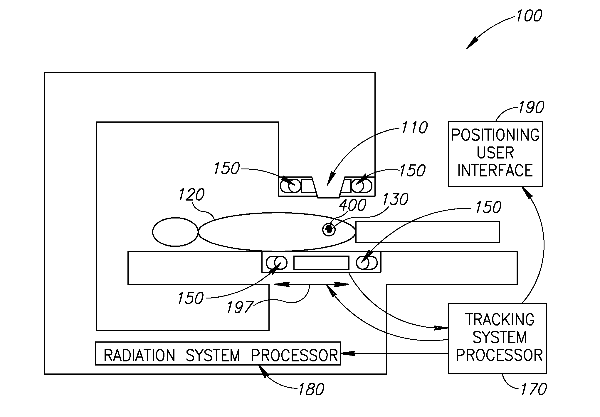
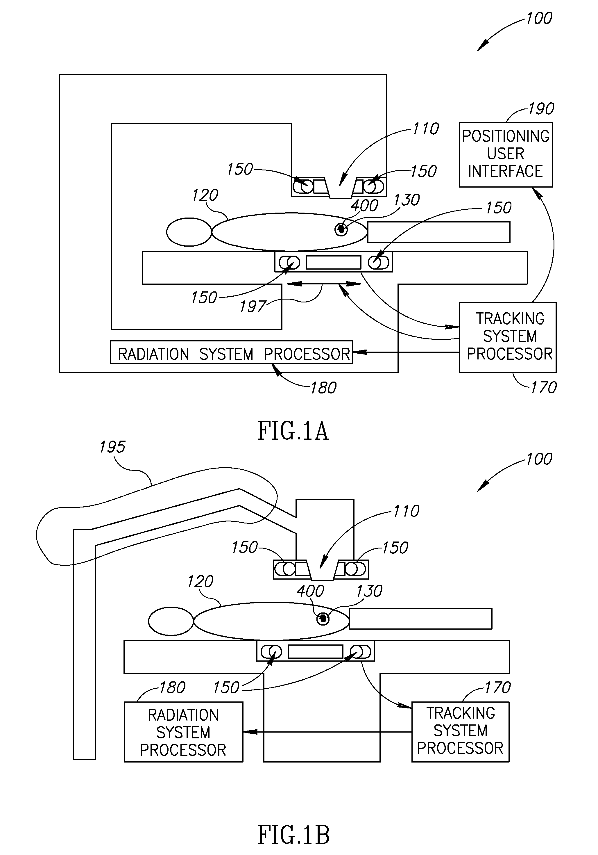
[0220]FIGS. 1A and 1B are schematic representations of exemplary radiation therapy systems 100 which rely upon radioactive disintegrations produced by an intrabody radiation source which can be in the form of a position indicator 400 located within a body of a patient 120. Position indicator 400 is optionally within, adjacent to or at a known geometric relationship with respect to a target tissue 130. Optionally, target tissue 130 is a tumor. Optionally, the implantation position and geometric relationship are selected ahead of time. Alternatively or additionally, the relationship may be determined after implanting, for example, by manual or automatic analysis of x-ray or CT images of the patient. Optionally, more than one marker is implanted, for example to assist in determining patient orientation.

[0221] In an exemplary embodiment of the invention, source 400 broadcasts its location radially outward as photons resulting from radioactive disintegrations. Optionally, a po...


PUM


Abstract

A method of guiding a tool, the method comprising: (a) implanting a source of radioactivity at a position having a geometric relationship to a target tissue; (b) determining at least an indication of a location of said source using at least one radioactivity detecting position sensor; and (c) positioning a tool at a desired relative location with respect to said target tissue based on said determined location.

Description

RELATED APPLICATION DATA [0001] This Application claims benefit under §119(e), directly or indirectly, from U.S. Provisional Applications: [0002] 60 / 773,931 filed on Feb. 16, 2006, entitled “Radiation Oncology Application”; [0003] 60 / 804,178 filed on Jun. 8, 2006, entitled “Radioactive Medical Implants”; [0004] 60 / 773,930 filed Feb. 16, 2006, entitled “Localization of a Radioactive Source”; [0005] The disclosures of these applications are fully incorporated herein by reference. [0006] This application is a continuation-in-part of: [0007] PCT / IL2005 / 000871 filed on Aug. 11, 2005, entitled “Localization of a Radioactive Source within a Body of a Subject”; and PCT / IL2005 / 001101 filed on Oct. 19, 2005; entitled “Tracking a Catheter Tip by Measuring its Distance From a Tracked Guide Wire Tip”. [0008] The disclosures of these applications are fully incorporated herein by reference. [0009] This Application is related to: [0010] U.S. Provisional Application 60 / 600,725 filed on Aug. 12, 2004...

Claims


Application Information

Patent Timeline
Patent Type & Authority Applications(United States)
IPC IPC(8): A61B5/05
CPCA61B5/1127A61B19/5244A61B19/54A61B2019/207A61B2019/5268A61N2005/1051A61B2019/542A61B2019/5487A61N5/1049A61N5/1067A61N5/1069A61B2019/5408A61B2034/2068A61B2090/392A61B34/20A61B2090/101A61B90/39A61B2090/3908A61B2090/3987
Inventor NEUSTADTER, DAVID MAIERKORNBLAU, GIORA
Owner NAVOTEK MEDICAL
Why Eureka
Try Eureka