Flexible valves

Inactive Publication Date: 2007-03-15
SEALED AIR U S
View PDF91 Cites 30 Cited by
  • Summary
  • Abstract
  • Description
  • Claims
  • Application Information

AI Technical Summary

Benefits of technology

[0009] b. a seal position to substantially

Problems solved by technology

One drawback associated with conventional flexible valves concerns the manner in which containers incorporating such valves may be deflated or emptied.
Such a technique can damage the internal components of the valve, which are generally formed of relatively thin flexib

Method used


Image

  • Flexible valves
  • Flexible valves
  • Flexible valves

Examples


Example

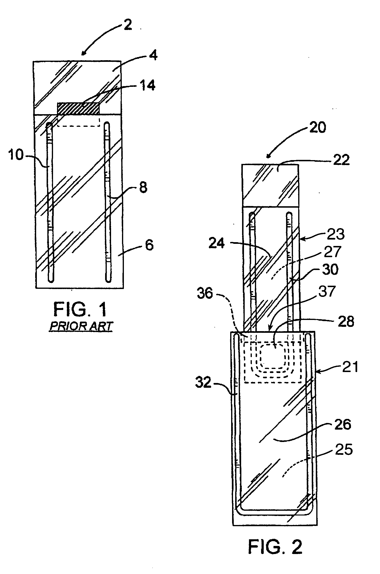
[0049] With reference to FIG. 1, there is pictured a flexible, self-sealing valve of the prior art designated generally by the reference numeral 2. The self-sealing valve in this figure is comprised of a first film ply of thermoplastic material 4 and a second film ply of thermoplastic material 6 entirely parallel and coplanar with each other. The first and the second film plies 4, 6 are secured together at weld lines 8, 10 along the longitudinal sides of the film plies and together define a channel. A heat resistant coating 14 is also pictured, applied to film ply 4. The heat resistant coating prevents the accidental closure of the channel when the valve is incorporated into an article by heat sealing means.

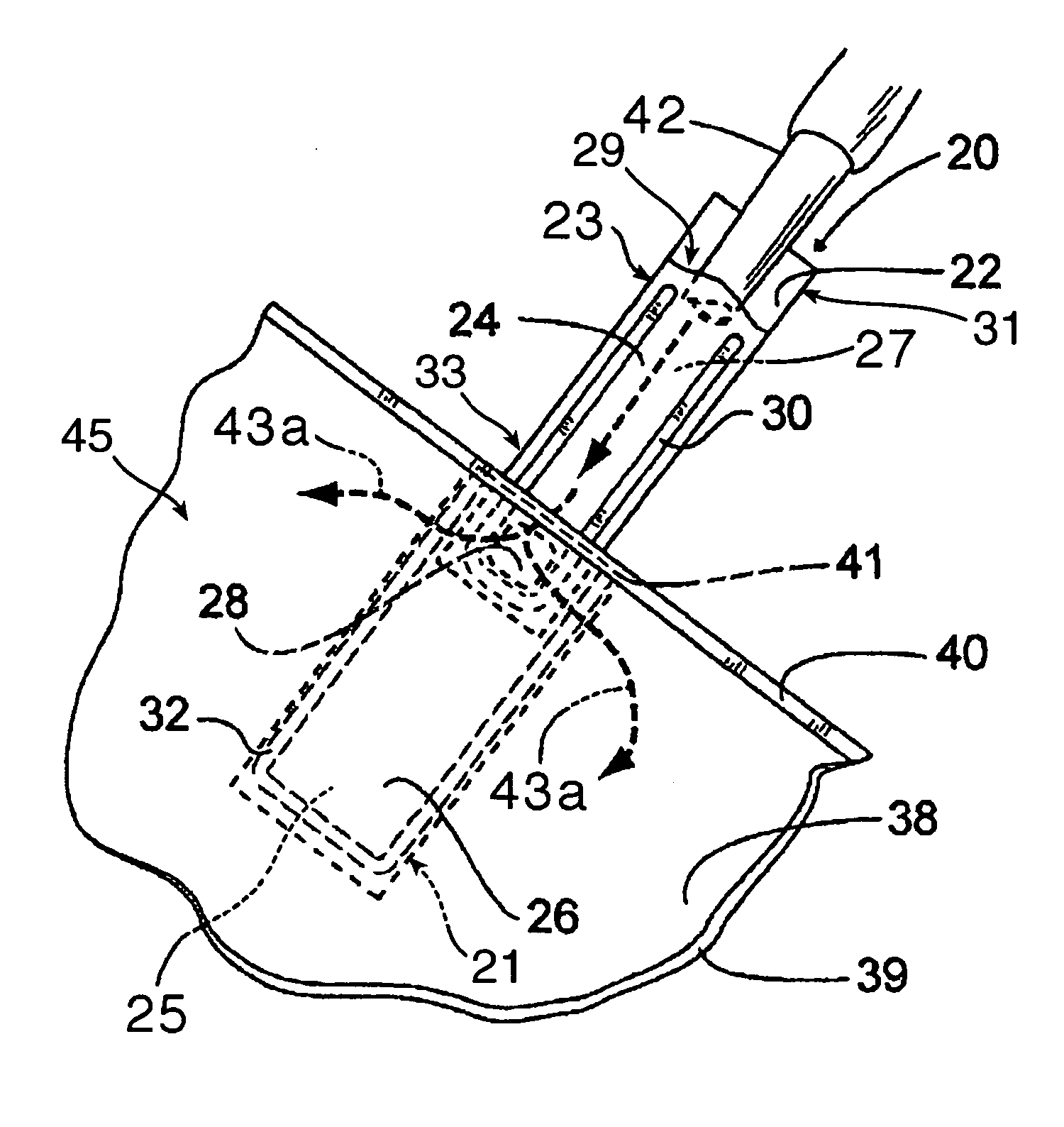
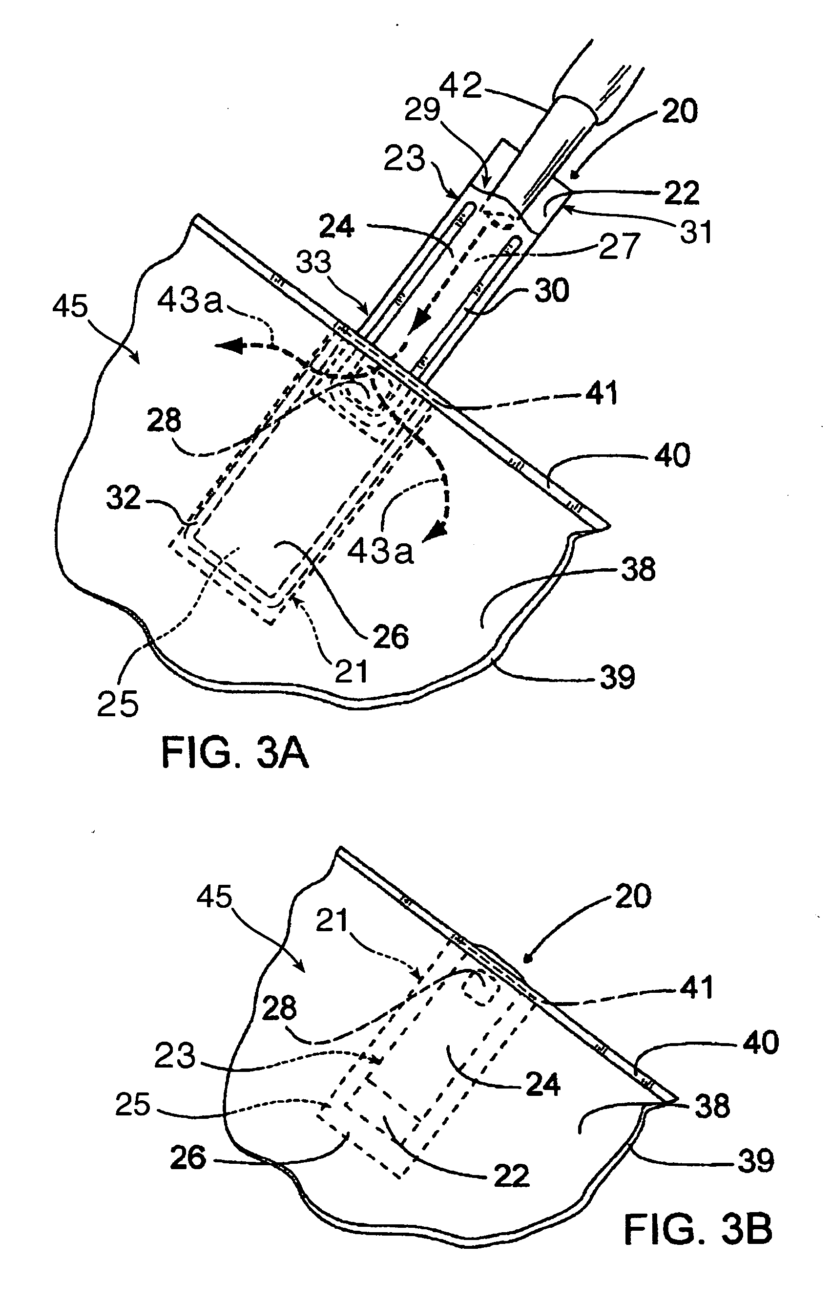
[0050] The operation of this flexible, flat valve of the prior art involves the injection of a gas, usually air, through the channel defined by film plies 4, 6 and welds 8, 10 into an article (not-pictured) to be inflated. Once the article is partially or wholly inflated, intern...


PUM

PropertyMeasurementUnit
Flexibilityaaaaaaaaaa

Abstract

A flexible valve includes two or more juxtaposed film plies joined together with one or more seals. The valve is movable between (1) an ingress position to allow fluid flow through the valve in a first direction, e.g., into a container with which the valve is associated; (2) a seal position to substantially prevent fluid flow through the valve; and (3) an egress position to allow fluid flow through the valve in a second direction, e.g., out of a container with which the valve is associated.

Description

[0001] This Application claims the benefit of U.S. Provisional Application No. 60 / 716,292, filed Sep. 12, 2005, the disclosure of which is hereby incorporated herein by reference thereto.BACKGROUND OF THE INVENTION [0002] The present invention relates to flexible, generally flat valve structures. More particularly, the present invention relates to flexible valves that contain an egress mechanism, which allows containers with which such valves are associated to be emptied of fluid contained therein. [0003] Simple and inexpensive flexible valves are well-known in the art. Such valves are generally constructed from two or more flexible films that are juxtaposed and sealed together to form a structure having a flat profile and an internal fluid-passage channel through which fluids may flow. Such valves are typically one-way, self-self sealing valves, which allow fluid flow in one direction but substantially prevent fluid flow in the opposite direction. In use, the valves are typically i...

Claims


Application Information

Patent Timeline
IPC IPC(8): F16K15/14
CPCB31B19/84B31B2219/9067B65D31/145F16K15/147B65D75/5872B65D77/225B65D81/052B65D75/5866B31B70/85Y10T137/7879
Inventor FRAYNE, SHAWN
Owner SEALED AIR U S
Why Eureka
Try Eureka