Setting tool

a technology of setting tool and setting energy, which is applied in the direction of portable percussive tools, boring/drilling equipment, portable drilling machines, etc., can solve the problems of increasing the reduction of setting energy, and achieve the effect of economic production, minimal additional costs, and increased costs

Active Publication Date: 2007-03-15
HILTI AG
View PDF31 Cites 7 Cited by
  • Summary
  • Abstract
  • Description
  • Claims
  • Application Information

AI Technical Summary

Benefits of technology

[0016] According to one advantageous embodiment of the inventive setting tool, the inclined surface is formed by a surface of the stop member. Because the stop member, which preferably is formed of metal such as, e.g., steel and is produced by turning, the inclined surface can be formed with a minimum of additional costs.
[0017] According to another advantageous embodiment of the present invention, the inclined surface is formed by a surface of...

Problems solved by technology

With one of respective cooperating surfaces forming an angle with a surface it cooperates with, excessive setting energy leads to an increase...

Method used


Image

  • Setting tool
  • Setting tool
  • Setting tool

Examples


Embodiment Construction

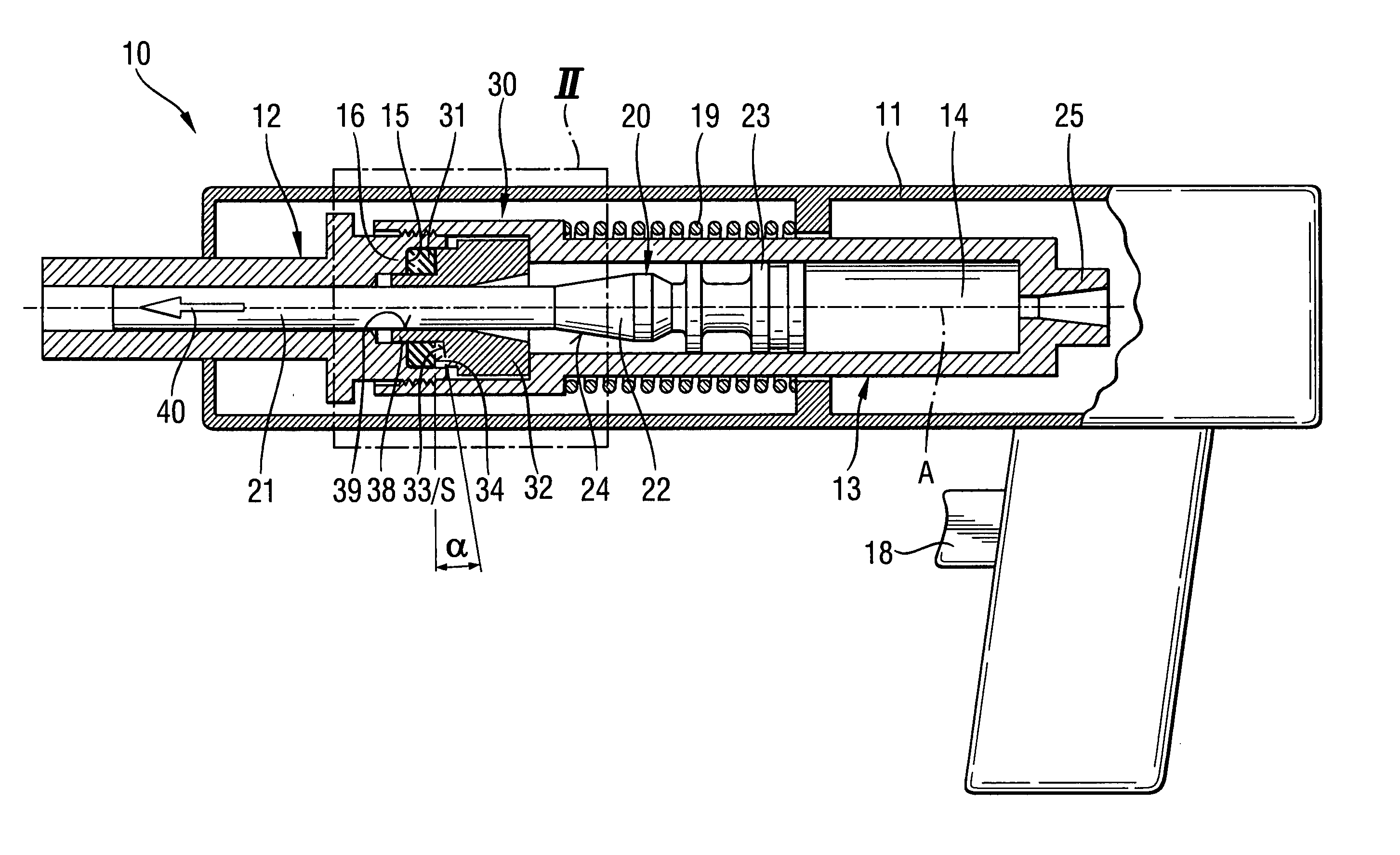
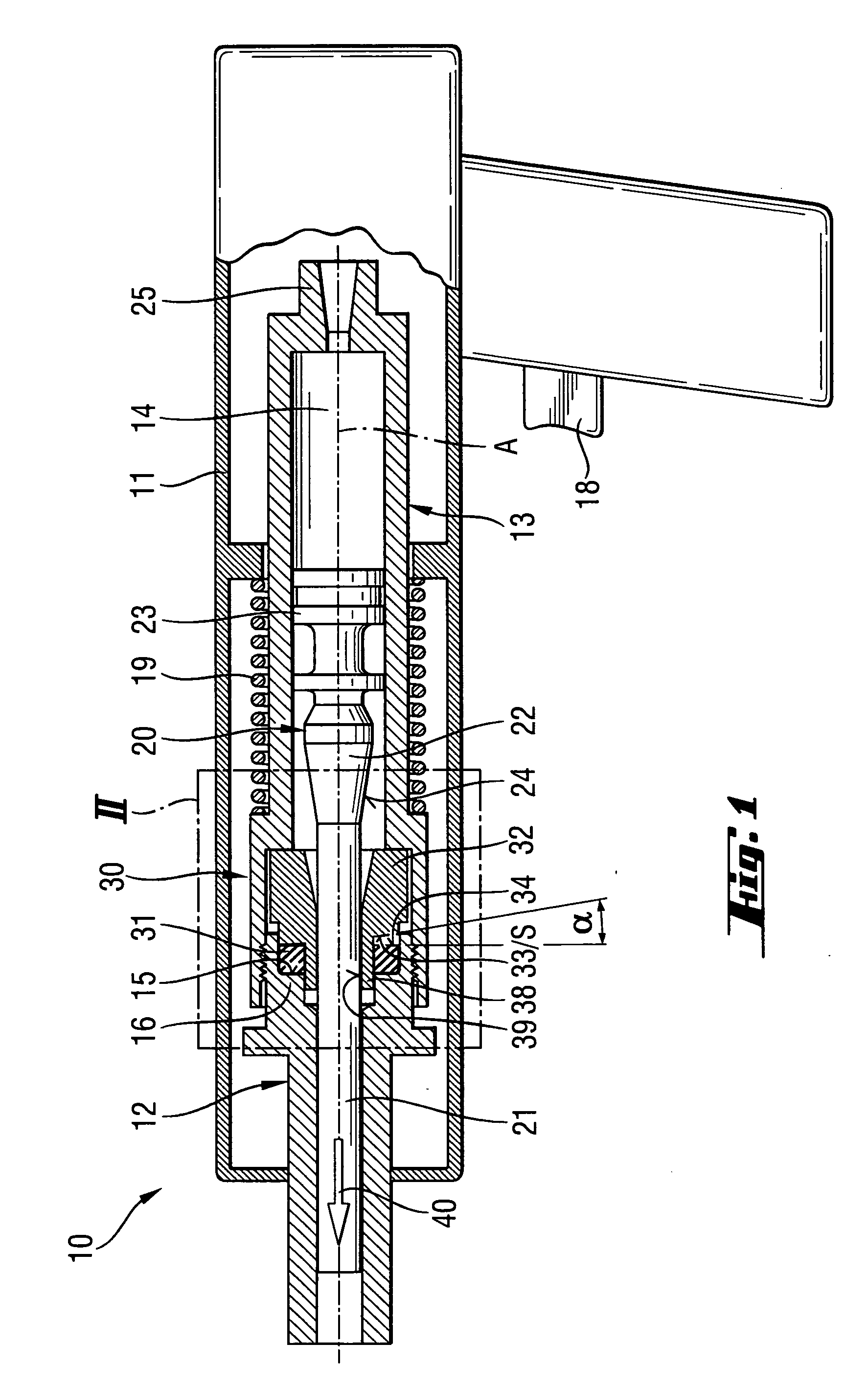
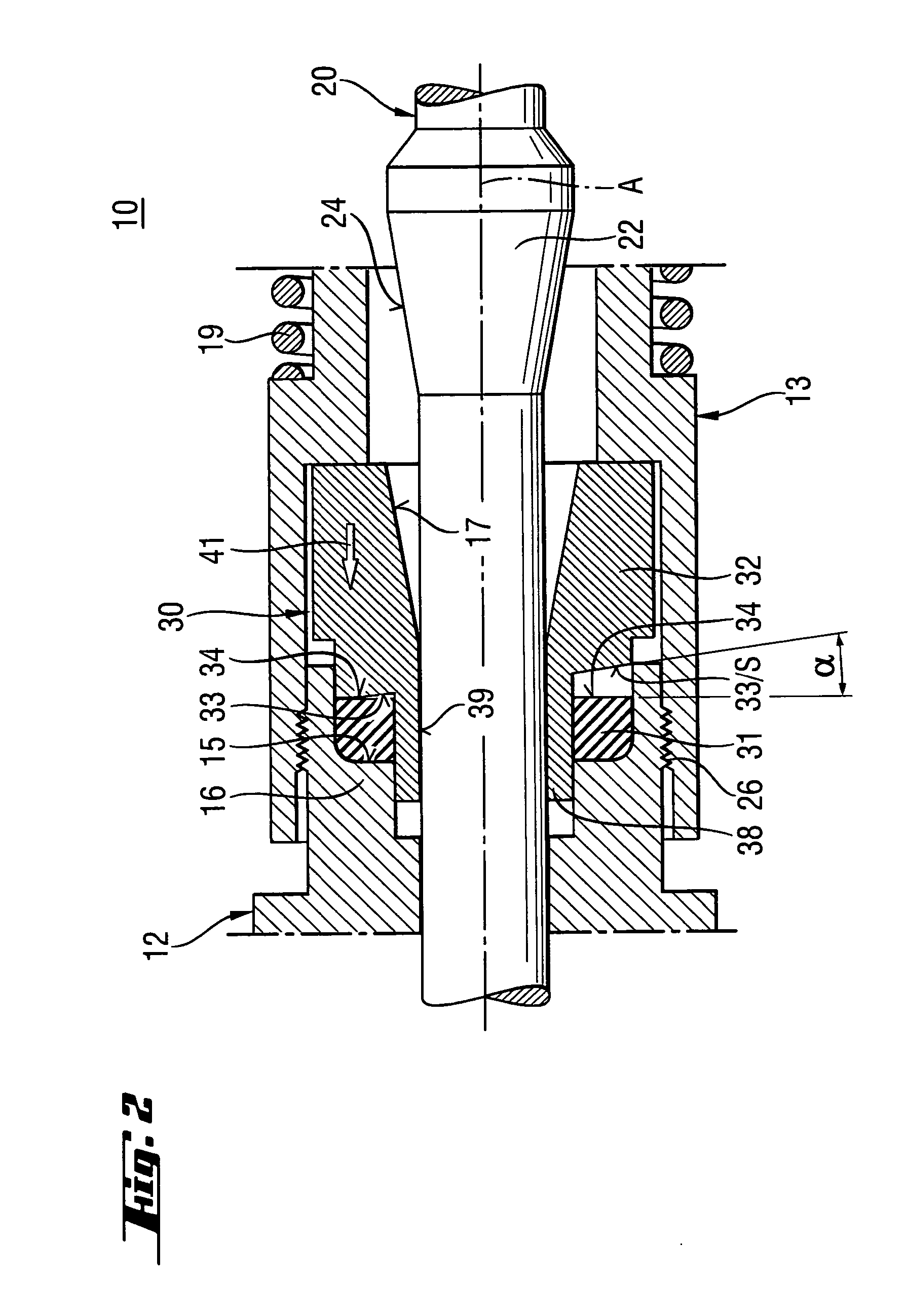
[0026] A setting tool 10 according to the present invention, which is shown in FIGS. 1-2, includes a piston stop device generally designated with a reference numeral 30. The setting tool 10 further includes a piston guide 13 which is arranged in one-or multi-part housing 11. The piston guide 13 has a hollow chamber 14 in which a setting piston 20 is displaceably arranged. The piston 20 is driven by a propellant or its reaction products, e.g., combustion gases or the like. The setting piston 20 has a piston stem 21 that adjoins, in a setting direction 40 of the setting tool 10, a piston head 23. On the piston stem 21, there is provided a piston collar 22 spaced from the piston head 23. The piston collar 22 has a counter-stop surface 24 extending in a direction of the piston stop device 30 and formed, in the embodiment of the setting tool 10 shown in the drawings, as a conical surface. The piston collar 22 can have a shape different from that shown in the drawings but is always arrang...


PUM

PropertyMeasurementUnit
Angleaaaaaaaaaa
Angleaaaaaaaaaa
Angleaaaaaaaaaa

Abstract

A setting tool for driving in fastening elements includes a setting piston (20) axially displaceable in a piston guide (13) which is adjoined by a bolt guide (12), and a piston stop device (30) for the setting piston (20) and arranged at an end region of the piston guide (13) adjacent to the bolt guide (12) and having a damping element (31) supported against a stop (15), and a stop member (32) for the setting piston (20) and adjoining the damping element (31) in a direction toward the piston guide (13), with the damping element (31), the stop member (32) and the stop (15) having respective surfaces (33, 34; 35, 36) arranged axially opposite each other at least one of which is formed as an inclined surface (S) forming with a respective opposite surface an angle of from 2° to 20°.

Description

BACKGROUND OF THE INVENTION [0001] 1. Field of the Invention [0002] The present invention relates to a setting tool for driving fastening elements in a constructional component and including a piston guide having a hollow chamber, a setting piston axially displaceable in the hollow chamber of the piston guide, a bolt guide adjoining the piston guide in a setting direction of the setting tool, and a piston stop device for the setting piston and arranged at an end region of the hollow chamber adjacent to the bolt guide, with the piston stop device having a damping element supported against a stop, and a stop member for the setting piston and adjoining the damping element in a direction toward the hollow chamber of the piston guide, and with the damping element, the stop member, and the stop having respective surfaces arranged axially opposite each other. [0003] 2. Description of the Prior Art [0004] Setting tools of the type described above can be driven with solid gaseous, fluid fuel...

Claims


Application Information

Patent Timeline
IPC IPC(8): B25C1/14
CPCB25C1/14
Inventor FRANZ, KARL
Owner HILTI AG
Why Eureka
Try Eureka