Zoom lens and image-pickup apparatus having the same

a technology of zoom lens and image pick-up apparatus, which is applied in the field of zoom lens, can solve the problems of difficult to suppress the variations of aberration due to zooming, the entire lens system is difficult to be miniaturized, and the increase of aberration due to vibration compensation, etc., and achieve the effect of efficient compensation for vibration

Active Publication Date: 2007-03-15
CANON KK
View PDF5 Cites 13 Cited by
  • Summary
  • Abstract
  • Description
  • Claims
  • Application Information

AI Technical Summary

Benefits of technology

[0018] An exemplary embodiment of the present invention is directed to a zoom lens where the load of a driving device, configured to compensate for vibration (image stabilizer), is small, and the entire apparatus can be miniaturized. Additionally an exemplary embodiment efficiently compensates for the vibration and can include an image-pickup apparatus having the zoom lens.

Problems solved by technology

Hence, when the lens is zoomed at a high ratio, the variations in aberration due to the zooming are difficult to be suppressed.
Since the displacement of the second lens group during zooming is comparatively large relative to the zoom ratio, the entire lens system is difficult to be miniaturized.
The vibration is compensated by parallel decentering part of the second lens group; however, when the lens is zoomed at a high ratio, the increasing tendency of aberration due to the vibration compensating has been shown.
Thus, a large load is applied to a drive system for correcting the blurring (compensating the vibration), resulting in an increasing tendency in size of the camera shake drive system.
When the vibration is compensated by decentering the lens, there can be a delayed response in decentering the lens.

Method used


Image

  • Zoom lens and image-pickup apparatus having the same
  • Zoom lens and image-pickup apparatus having the same
  • Zoom lens and image-pickup apparatus having the same

Examples


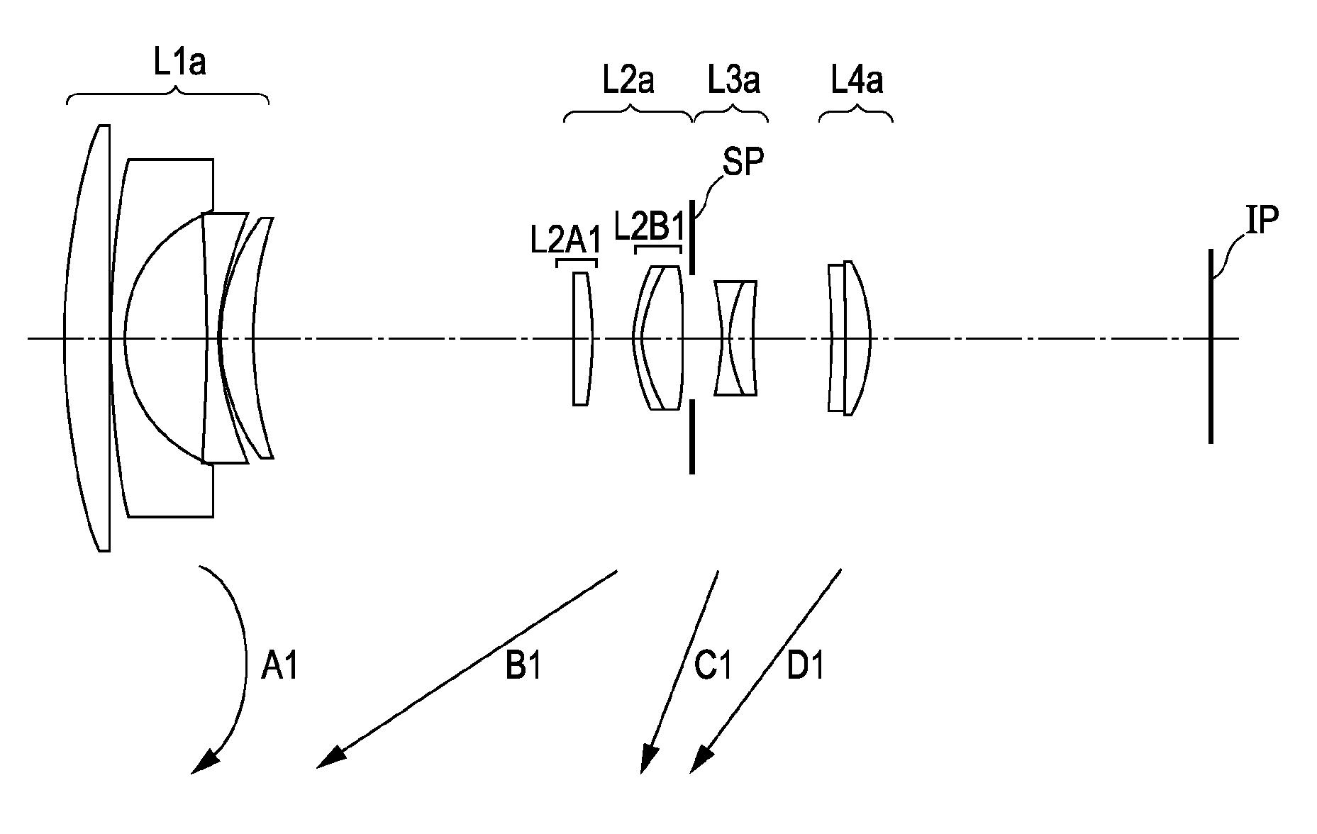
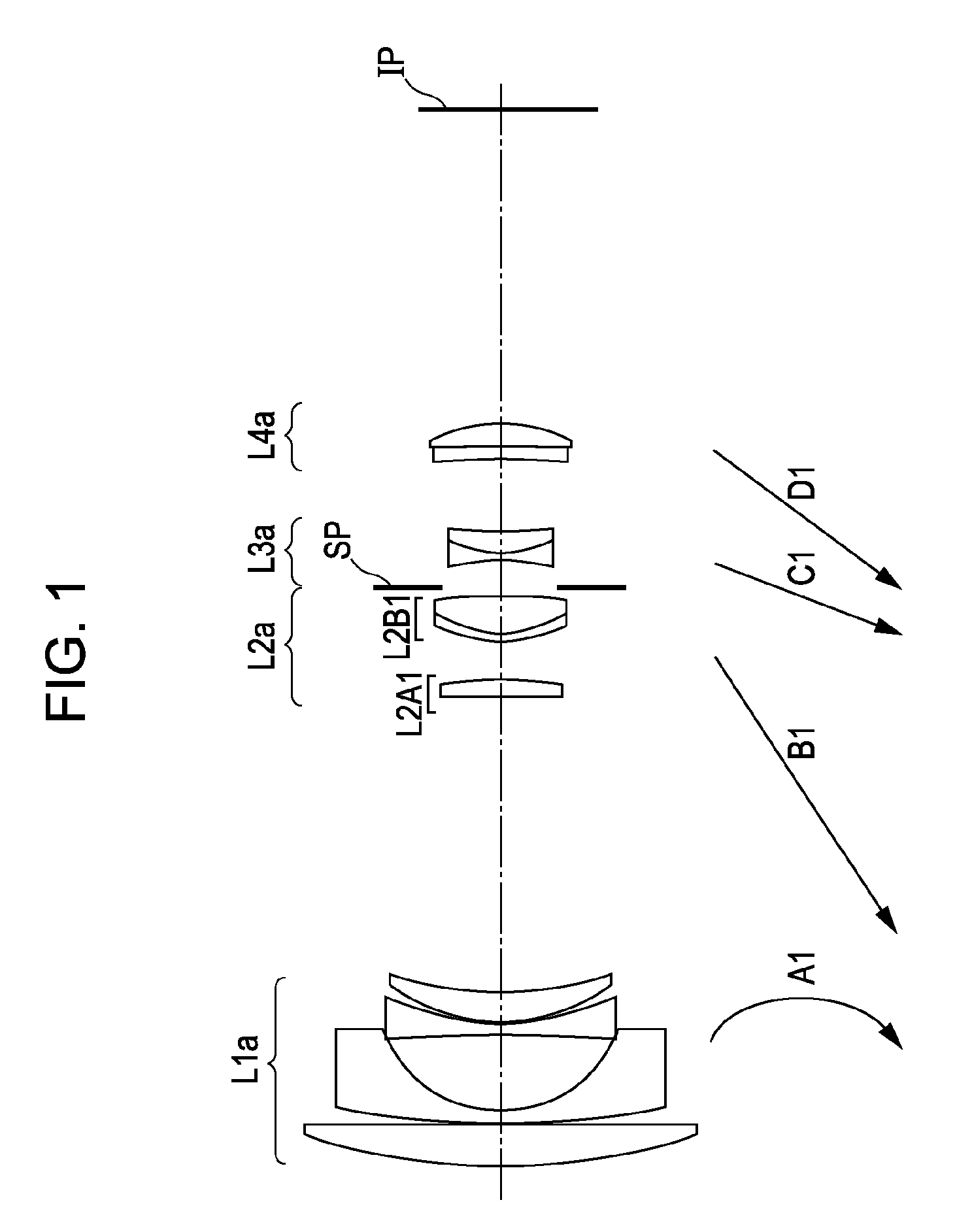
numerical examples 1

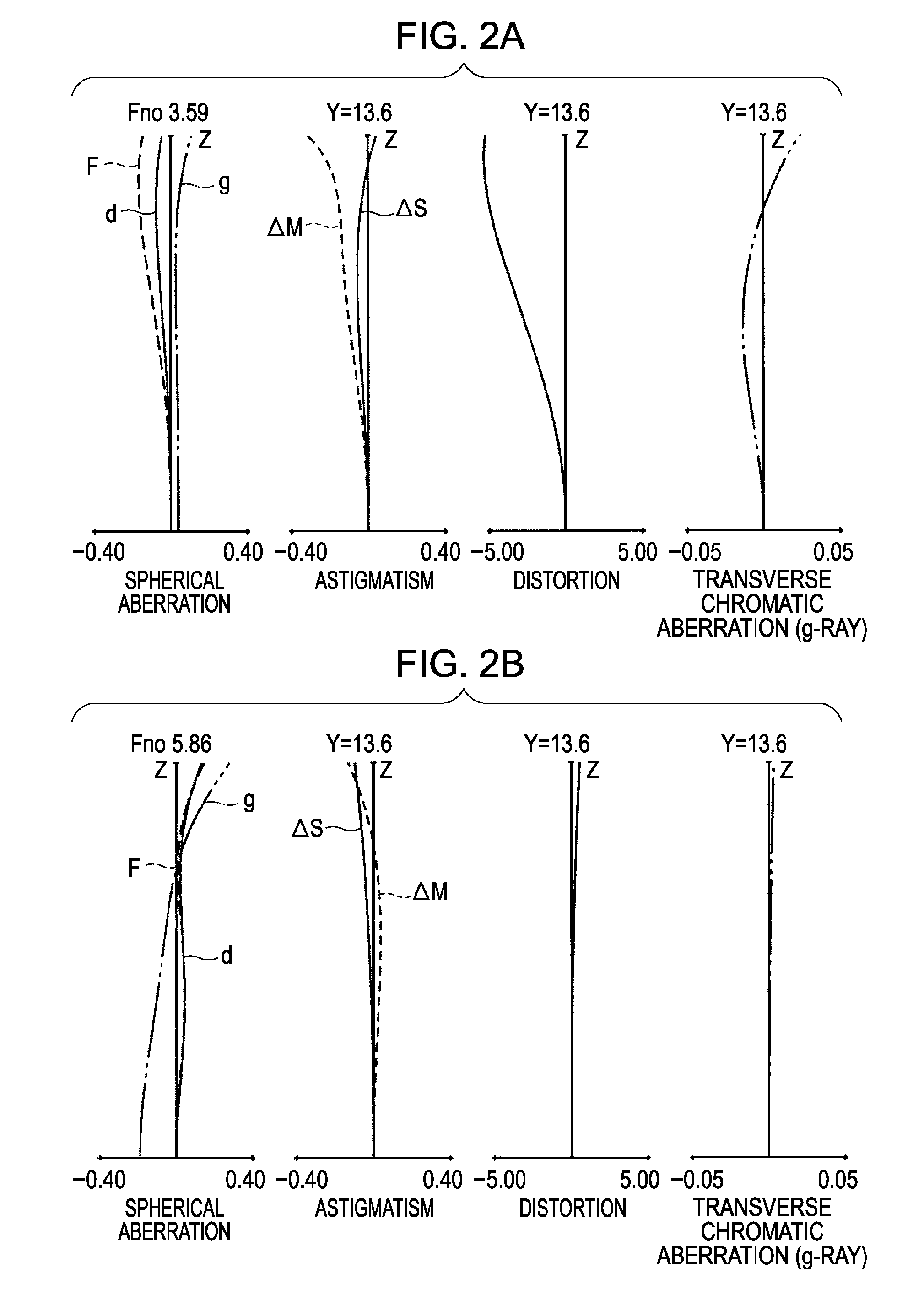
f=17.50˜53.00 Fno=3.59˜5.86 2 =75.8°˜28.8°

R 1=74.641 D 1=4.50 N 1=1.516330 ν 1=64.1

R 2=−3856.041 D 2=0.15

R 3=98.417 D 3=1.60 N 2=1.622992 ν 2=58.2

R 4=14.489 D 4=8.52

R 5=−127.608 D 5=1.20 N 3=1.622992 ν 3=58.2

R 6=27.528 D 6=0.15

R 7=21.526 D 7=3.40 N 4=1.846660 ν 4=23.8

R 8=42.071 D 8=VARIABLE

R 9=−531.961 D 9=1.70 N 5=1.518229 ν 5=58.9

R10=−36.156 D10=4.53

R11=16.829 D11=0.80 N 6=1.846660 ν 6=23.9

R12=12.056 D12=4.20 N 7=1.487490 ν 7=70.2

R13=−71.553 D13=1.00

R14=APERTURE STOP D14=VARIABLE

R15=−28.778 D15=0.75 N 8=1.647689 ν 8=33.8

R16=12.243 D16=2.40 N 9=1.761821 ν 9=26.5

R17=51.593 D17=VARIABLE

R18=−62.665 D18=1.30 N10=1.491710 ν10=57.4

[0118] R19=−140.261 D19=−0.07

R20=1237.920 D20=2.69 N11=1.487490 ν11=70.2

R21=−17.585

\FOCAL LENGTH 17.50 31.07 53.00 VARIABLE SPACE\

D 8 33.74 13.03 3.04

R20=417.340 D20=3.80 N11=1.487490 ν11=70.2

R21=−18.474

\FOCAL LENGTH 18.69 32.08 53.27 VARIABLE SPACE\

D 8 33.62 13.53 3.23

D14 3.30 6.19 8.96

D17 7.34 4.45 1.68

...

numerical examples 3

f=18.62˜53.32 Fno=3.63˜5.86 2ω=72.4°˜28.7°

R 1=70.299 D 1=3.40 N 1=1.516330 ν 1=64.1

R 2=601.574 D 2=0.15

R 3=85.189 D 3=1.60 N 2=1.622992 ν 2=58.2

R 4=14.573 D 4=8.08

R 5=−131.403 D 5=1.20 N 3=1.622992 ν 3=58.2

R 6=26.414 D 6=0.15

R 7=21.357 D 7=3.40 N 4=1.805181 ν 4=25.4

R 8=48.045 D 8=VARIABLE

D14 3.30 6.68 10.13

D17 8.24 4.86 1.41

numerical examples 2

f=18.69˜53.27 Fno=3.63˜5.86 2ω=72.2°˜28.7°

R 1=80.198 D 1=3.40 N 1=1.516330 ν 1=64.1

R 2=1485.520 D 2=0.15

R 3=74.916 D 3=1.60 N 2=1.622992 ν 2=58.2

R 4=14.601 D 4=7.99

R 5=−141.698 D 5=1.20 N 3=1.622992 ν 3=58.2

R 6=25.795 D 6=0.15

R 7=21.179 D 7=3.40 N 4=1.805181 ν 4=25.4

R 8=46.880 D 8=VARIABLE

R 9=−302.692 D 9=1.90 N 5=1.487490 ν 5=70.2

R10=−34.091 D10=4.20

R11=16.673 D11=0.80 N 6=1.846660 ν 6=23.9

R12=12.277 D12=4.50 N 7=1.487490 ν 7=70.2

R13=−73.294 D13=1.00

R14=APERTURE STOP D14=VARIABLE

R15=−29.161 D15=0.75 N 8=1.639799 ν 8=34.5

R16=12.672 D16=2.60 N 9=1.784723 ν 9=25.7

R17=43.512 D17=VARIABLE

R18=−96.235 D18=1.50 N10=1.583060 ν10=30.2

[0119] R19=−437.245 D19=0.03

R 9=−212.350 D 9=1.90 N 5=1.516330 ν 5=64.1

R10=−33.748 D10=4.20

R11=16.638 D11=0.80 N 6=1.846660 ν 6=23.9

R12=12.089 D12=4.50 N 7=1.487490 ν 7=70.2

R13=−67.351 D13=1.00

R14=APERTURE STOP D14=VARIABLE

R15=−27.965 D15=0.75 N 8=1.639799 ν 8=34.5

R16=12.432 D16=2.60 N 9=1.784723 ν 9=25.7

R17...


PUM


Abstract

At least one exemplary embodiment is directed to a zoom lens which includes first to fourth lens groups, each moving and having negative, positive, negative, and positive refractive power, arranged from an object to an image in that order. The second lens group includes a second A lens component composed of a single positive lens, and a second B lens component composed of a negative lens and a positive lens with positive refractive power as a whole, arranged from the object to the image in that order. The second A lens component displaces images in a direction substantially perpendicular to an optical axis by having a component of it's displacement perpendicular to the optical axis, and the zoom lens satisfies the following condition: 0.2<f2/f2A<0.6, where f2A and f2 are focal lengths of the second A lens component and the second lens group, respectively.

Description

BACKGROUND OF THE INVENTION [0001] 1. Field of the Invention [0002] The present invention relates to zoom lenses, more particularly though not exclusively, to zoom lenses used in image-pickup apparatuses. [0003] 2. Description of the Related Art [0004] Recently, image-pickup apparatuses, such as a photographic camera, a video camera, and a digital camera, have been demanded to have higher quality images. [0005] Furthermore, because of the expansion in shooting conditions, it would be useful for the lenses used in these apparatuses to be zoom lenses having image stabilizing performances for correcting blurring due to camera shake. [0006] A method of compensating vibration includes decentering selected lens groups arranged in parallel with a direction substantially perpendicular to an optical axis. This method needs no additional optical system for compensating vibration. [0007] This method also has merits that the lens groups for vibration compensating can be mostly simplified and an...

Claims


Application Information

Patent Timeline
Patent Type & Authority Applications(United States)
IPC IPC(8): G02B15/14
CPCG02B15/177G02B15/144511
Inventor NISHIMURA, TAKESHI
Owner CANON KK
Why Eureka
Try Eureka