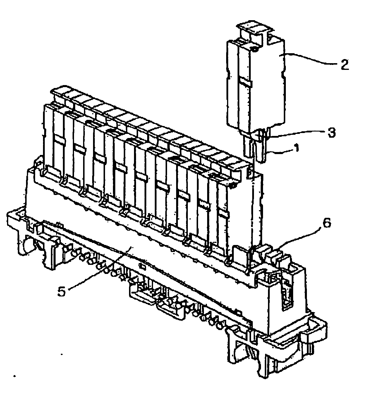
Communication-circuit line protector

a communication circuit and line protector technology, applied in emergency protective arrangements for limiting excess voltage/current, electrical apparatus casings/cabinets/drawers, electrical apparatus contruction details, etc., can solve problems such as inability to release generated heat, communication-circuit line protectors may not perform a normal function, and means for checking disorder or failure of communication-circuit line protectors, so as to facilitate checking disorder or failure, effectively release heat, and increase contact strength

Inactive Publication Date: 2007-03-15
JOUNG JAE HAN
View PDF12 Cites 0 Cited by
  • Summary
  • Abstract
  • Description
  • Claims
  • Application Information

AI Technical Summary

Benefits of technology

[0017] In the communication-circuit line protector according to the present invention, since a plurality of the openings are disposed on a side of the housing, it is possible to easily check a disorder or failure of the communication-circuit line protector before the time of delivering or at the time of using the line protector by using the openings, and it is possible to effectively release heat generated from an inner portion of the housing of the communication-circuit line protector through the openings.
[0018] In addition, since the elastic member is additionally disposed to protrude from one side of the PCB, the conduction member can be connected to the port with a more increased contact strength, so that it is possible to effectively reduce heat caused from an ohmic resistance of a contact po

Problems solved by technology

Therefore, the generated heat cannot be released, so that the communication-circuit line protector may not perform a normal function.
In addition, means for checking a disorder or failure of the communication-circuit line protector before the time of delivering or at the time of using the communication-circ

Method used


Image

  • Communication-circuit line protector
  • Communication-circuit line protector
  • Communication-circuit line protector

Examples


Embodiment Construction

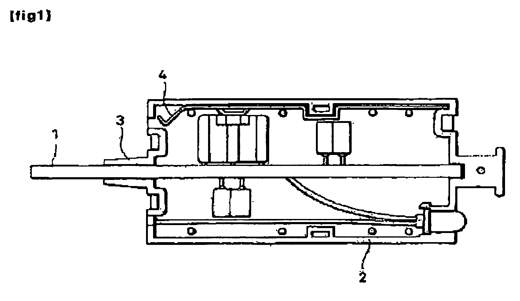
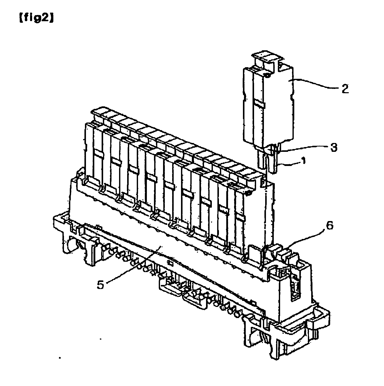
[0030] Hereinafter, preferred embodiments of the present invention are described with reference to the accompanying drawings. FIG. 3a is an exploded view of a communication-circuit line protector according to an embodiment of the present invention. FIG. 3b is an assembled view of the communication-circuit line protector according to the embodiment of the present invention. FIG. 4 is a detailed view showing a connecting protrusion and a connecting groove disposed in a lower portion of the communication-circuit line protector according to the embodiment of the present invention. FIG. 5 is a view showing a state where the communication-circuit line protectors according to the embodiment of the present invention are connected to ports provided to a port unit.

[0031] As shown in FIGS. 3a to 5, the communication-circuit line protector 100 according to the embodiment of the present invention includes openings 23a, 23b, 23c, and 23d. The openings 23a, 23b, 23c, and 23d are provided at a sid...


PUM


Abstract

A communication-circuit line protector capable of maintaining reliable connection to a port unit of a communication system, easily checking a disorder or failure of the communication-circuit line protector, and effectively releasing heat generated from an inner portion of the communication-circuit line protector is provided. The communication-circuit line protector include: a housing having a plurality of openings disposed on a side thereof; a ground pin provided to an inner side of the housing, the ground pin having an elastic end portion which cooperates with a lower-side inner wall of the housing opposite thereto to be in close contact with a ground portion, thereby maintain reliable ground contact; and a PCB having the ground pin attached to one side thereof and a conduction member provided to a lower end portion thereof, thereby maintaining good connection at a time of connection to a port.

Description

CROSS-REFERENCES TO RELATED PATENT APPLICATION [0001] This application claims the benefits of Korean Utility Model Application No 20-2005-0026110, filed on Sep. 9, 2005, and Korean Utility Model Application No. 20-2006-0001762, filed on Jan. 20, 2006 respectively in the Korean Intellectual Property Office, the disclosures of which are incorporated herein in their entireties by reference. BACKGROUND OF THE INVENTION [0002] 1. Field of the Invention [0003] The present invention relates to a communication-circuit line protector, and more particularly, to a communication-circuit line protector capable of maintaining reliable connection to a port unit of an apparatus in a communication system, easily checking a disorder or failure of the communication-circuit line protector, and effectively releasing heat generated from an inner portion of an housing of the communication-circuit line protector. [0004] 2. Description of the Related Art [0005] Generally, in a communication network system, ...

Claims


Application Information

Patent Timeline
IPC IPC(8): H02H9/06
CPCH01T4/06H01T4/04
Inventor JONG, JAE-HAN
Owner JOUNG JAE HAN
Why Eureka
Try Eureka