Sensor-equipped rolling bearing assembly

a technology of rolling bearings and sensors, applied in the direction of instruments, force/torque/work measurement apparatuses, transportation and packaging, etc., can solve the problems of increased assembly steps and complicated assembly work, and achieve the effect of convenient assembly

Inactive Publication Date: 2007-03-15
JTEKT CORP
View PDF6 Cites 27 Cited by
  • Summary
  • Abstract
  • Description
  • Claims
  • Application Information

AI Technical Summary

Benefits of technology

[0006] In view of the foregoing, the invention has been accomplished and has an object to provide a sensor-equipped rolling bearing asse

Problems solved by technology

This results in a complicated assembly work.
This

Method used


Image

  • Sensor-equipped rolling bearing assembly
  • Sensor-equipped rolling bearing assembly
  • Sensor-equipped rolling bearing assembly

Examples


Embodiment Construction

[0063] A sensor-equipped rolling bearing assembly (hereinafter, also referred to simply as “bearing assembly”) according to an embodiment of the invention will hereinbelow be described with reference to the accompanying drawings.

Bearing Assembly in a First Aspect

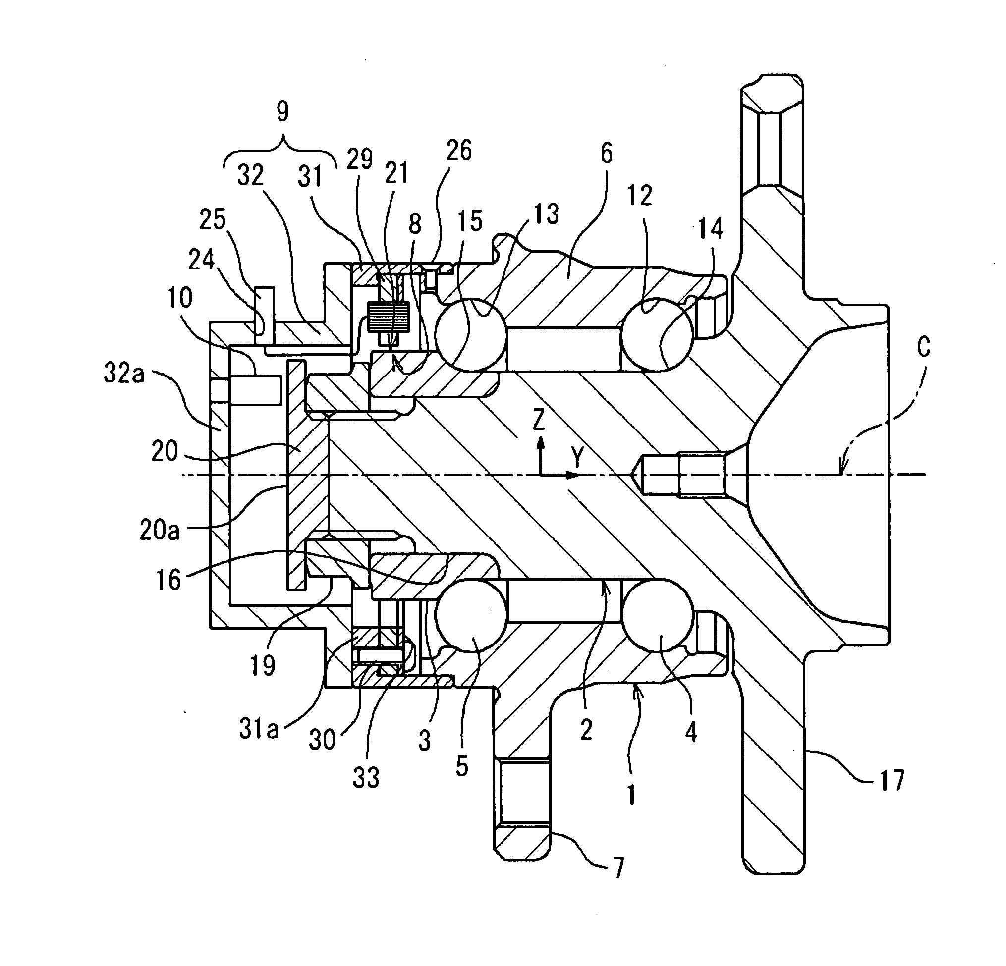
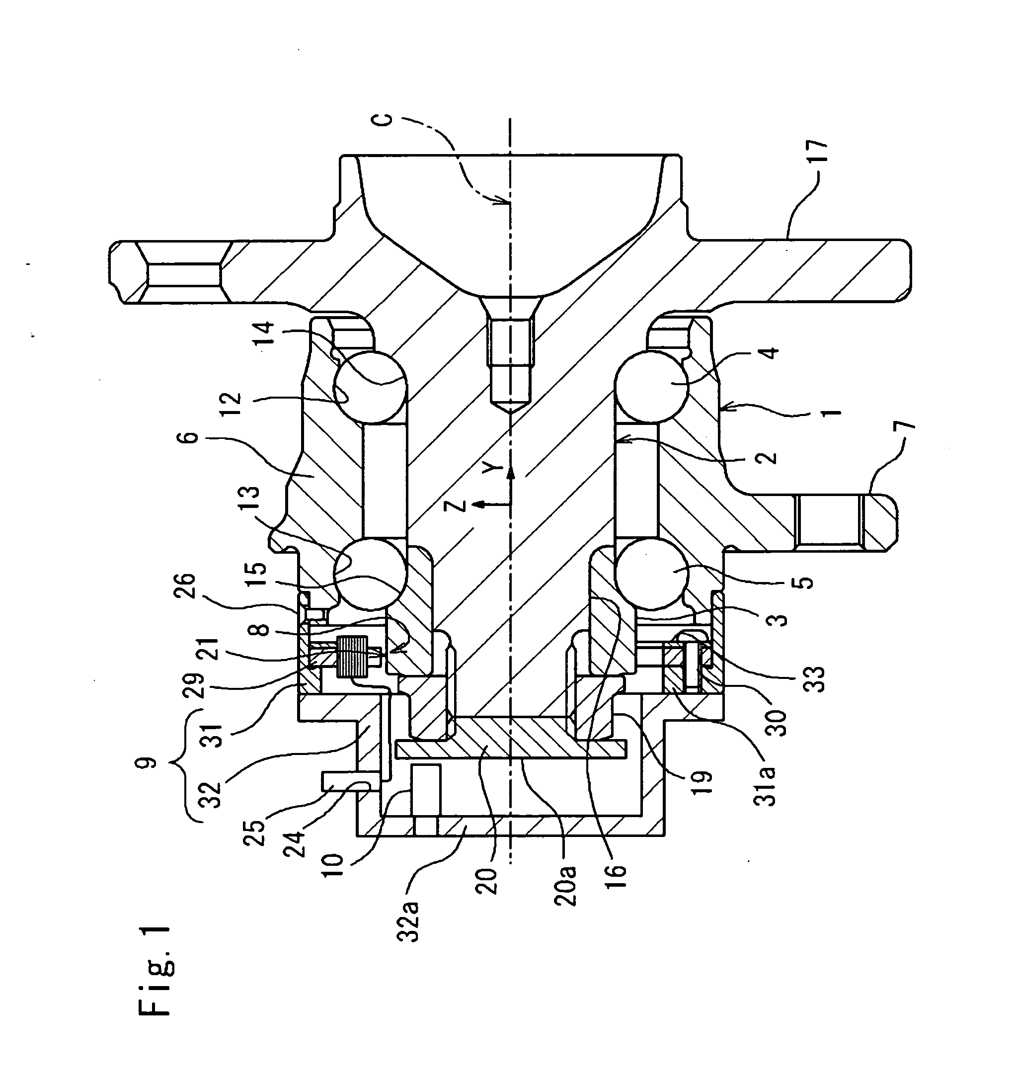
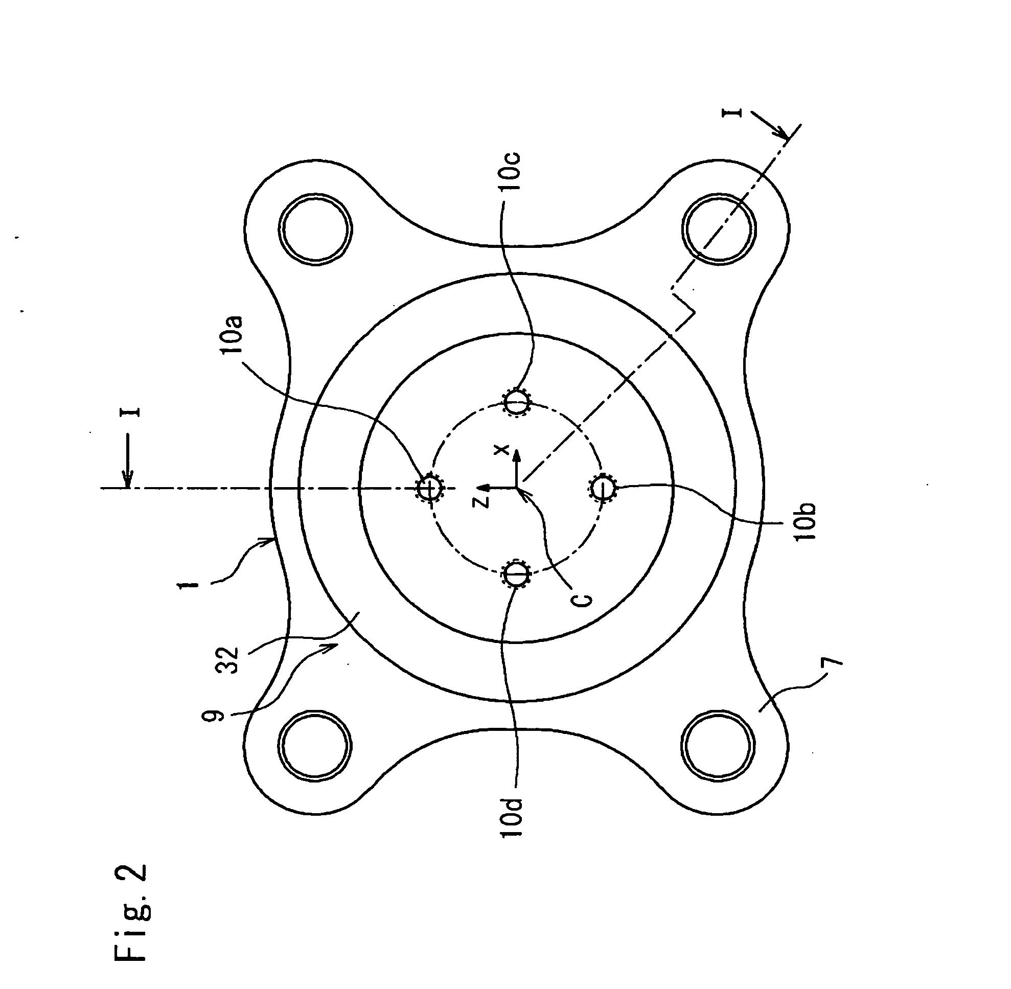
[0064]FIG. 1 is a sectional view showing a bearing assembly according to one embodiment of a first aspect of the invention. FIG. 2 is a view of this bearing assembly as seen from an inboard side along an axial direction thereof. In FIG. 1, the right-hand side is an outboard side with respect to a vehicle, whereas the left-hand side is an inboard side with respect to the vehicle.

[0065] The bearing assembly according to the embodiment includes: a cylindrical outer ring 1; an inner shaft 2 inserted through the outer ring 1; an inner ring member 3 fitted about an inboard end of the inner shaft 2; double rows of rolling elements 4, 5, each row including plural balls. These components constitute a double-row angular ball beari...


PUM


Abstract

A sensor-equipped rolling bearing assembly includes: a cylindrical fixed bearing ring fixed to a vehicle body; a rotary bearing ring rotatably inserted through the fixed bearing ring and having a wheel-mounting portion on an outboard side thereof; and plural rows of rolling elements rollably interposed between these bearing rings. The bearing assembly is provided with a case member having plural displacement sensors which are circumferentially arranged at predetermined space intervals and which detect gaps between themselves and an outside surface of an inboard end of the rotary bearing ring. The case member is mounted to the inboard end of the fixed bearing ring.

Description

BACKGROUND OF THE INVENTION [0001] The present invention relates to a sensor-equipped rolling bearing assembly used for rotatably supporting a wheel of a vehicle such as an automotive vehicle. [0002] Modern automotive vehicles require a variety of information pieces for providing operation control while the vehicles are moving, the information pieces including, for example, load acting on the road wheel, the number of revolutions thereof. For acquisition of such information pieces, a proposal has been made to mount a sensor to a rolling bearing assembly to which the wheel of the vehicle is mounted. [0003] The conventionally known sensor-equipped rolling bearing assemblies include a bearing assembly which includes: a cylindrical fixed bearing ring fixed to a vehicle body; a rotary bearing ring which is disposed radially inwardly of the fixed bearing ring and to which the wheel is mounted; and plural rows of rolling elements rollably interposed between these bearing rings. This bearin...

Claims


Application Information

Patent Timeline
IPC IPC(8): F16C41/04
CPCB60B27/0005B60B27/0068B60B27/0094F16C2326/02G01L5/0023F16C33/723F16C19/522F16C19/186
Inventor MOTOHASHI, NOBUTSUNAUEYAMA, HIROCHIKAMIYAGAWA, YASUKATAKOUDUKI, KENICHITANIGUCHI, MANABU
Owner JTEKT CORP
Why Eureka
Try Eureka