

Optical transceiver
- Summary
- Abstract
- Description
- Claims
- Application Information
AI Technical Summary
Benefits of technology
Problems solved by technology
Method used
Image

Examples
first embodiment
[0027] Construction of Optical Transceiver
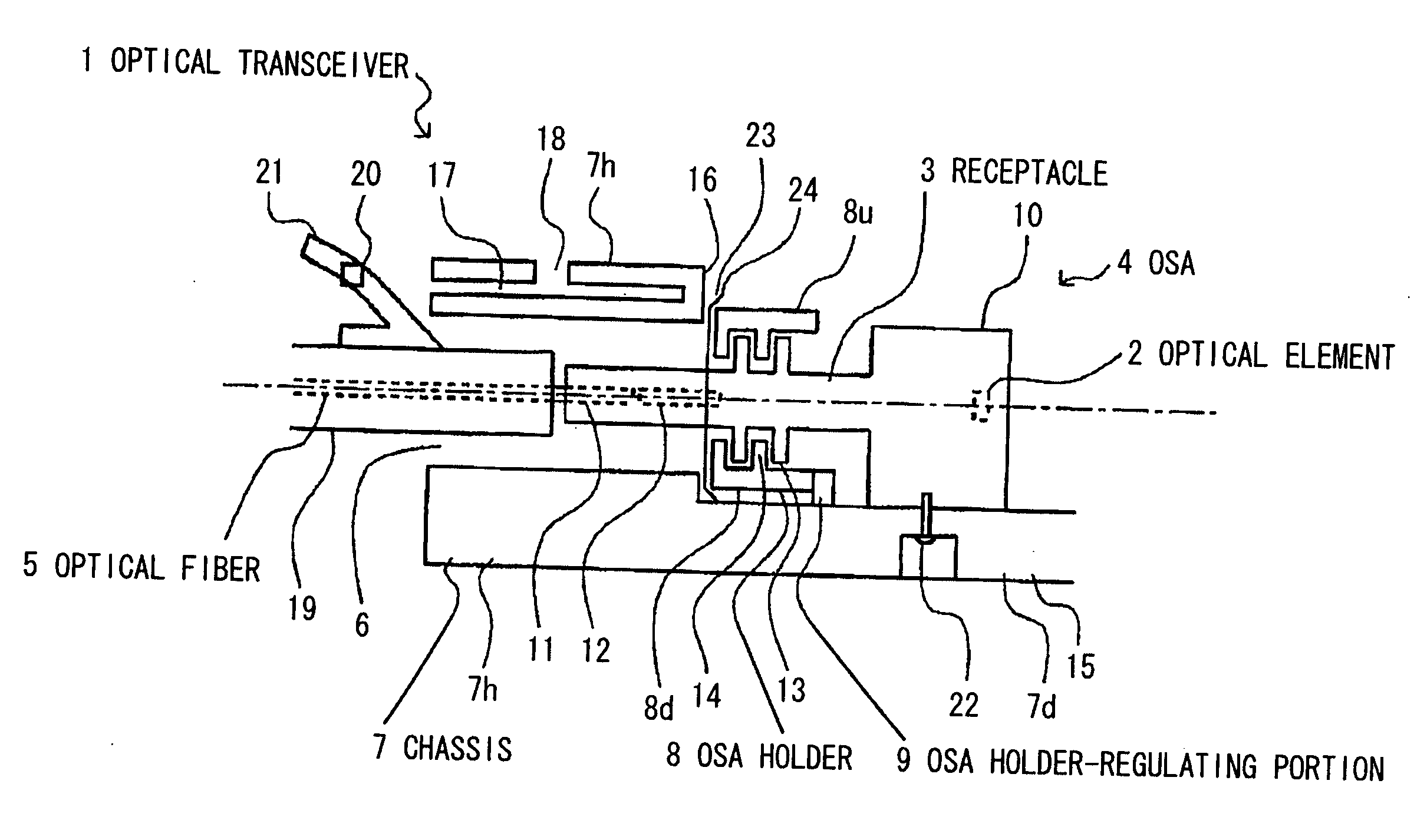
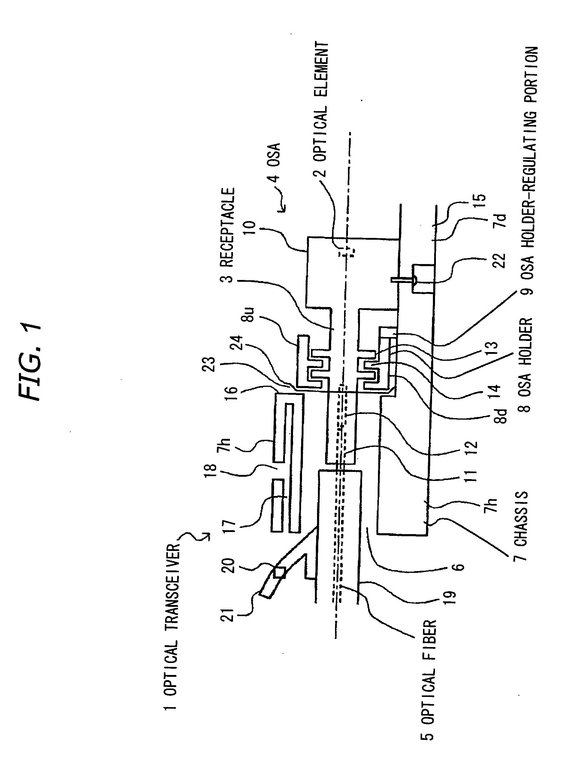
[0028] As shown in FIG.1, an optical transceiver 1 according to the invention comprises an optical subassembly (OSA) 4 equipped with a built-in optical element 2 and with a cylindrical receptacle 3 for conducting an optical path from the optical element 2, a chassis 7 with an entrance 6 formed for inserting an external optical fiber 5 to be connected to the above-mentioned optical path, an OSA holder 8 engaged with the receptacle 3 for holding the OSA 4 and accommodated in contact with an inside portion of the chassis 7 for accommodating and fixing the OSA 4 in the chassis 7, and an OSA holder-regulating portion 9 formed in the chassis 7 so as to be positioned opposite the entrance 6, i.e., on the right side in FIG. 1, relative to the OSA holder 8, to regulate the OSA holder 8.
[0029] OSA
[0030] Specifically, the OSA 4 is constructed by integrally attaching the cylindrical receptacle 3 to an optical module 10 that comprises the optical elem...
second embodiment
[0056]FIG. 5 is a sectional side view showing an OSA holder and an OSA in the second preferred embodiment according to the invention.
[0057] Although in FIG. 1 the positioning flange 13 of the receptacle 3 and the mated flange 14 of the OSA holder 8 have end faces all perpendicular to the optical axis, a particular end face is provided to be inclined in this embodiment.
[0058] As shown in FIG. 5, two positioning flanges 13 of a receptacle 3 have end faces all perpendicular to the optical axis. But one of two mated flanges 14 of an OSA holder 8 has an OSA holder-regulating portion 9 side end face 14a that is formed to be inclined, so that the one mated flange 14 is tapered. For this reason, the shorter the distance from the end face 14a to the axis of the receptacle 3, the larger the spacing between the end face 14a to an end face 13a of the positioning flange 13 gradually becomes. The OSA holder 8 is shown as the lower piece 8d only shown in FIG. 1, but the upper piece 8u, which is ...
third embodiment
[0063]FIG. 6 is a sectional side view showing an OSA holder and an OSA in the third preferred embodiment of the invention.
[0064] As shown in FIG. 6, two mated flanges 14 of an OSA holder 8 have end faces all perpendicular to the optical axis. But one of two positioning flanges 13 of a receptacle 3 has an entrance 6 side end face 13a that is formed to be inclined, so that the one positioning flange 13 is tapered. For this reason, the larger the distance from the axis of the receptacle 3 to an end face 14a of the mated flange 14, the larger the spacing between the end face 13a to the end face 14a gradually becomes.
[0065] Here, let the shortest distance from the end face 13b to end face 13a in the receptacle 3 be D, the longest distance from the end face 13b to the end face 13a in the receptacle 3E, and the optical-axial length of the mated flange 14 (i.e., the distance from the end face 14b to the end face 14a) in the OSA holder 8F, then
[0066] F≦E, F≧D, α=0
[0067] In the embodiment...
PUM
 Abstract
Description
Claims
Application Information