
Condenser

a condenser and condenser technology, applied in the field of condensers, can solve the problems of undesirable fixing and looseness, and achieve the effect of preventing the concentration of stress in the root portion

Inactive Publication Date: 2007-03-22
CALSONIC KANSEI CORP
View PDF7 Cites 10 Cited by
  • Summary
  • Abstract
  • Description
  • Claims
  • Application Information

AI Technical Summary

Benefits of technology

[0009] Therefore, the condenser can temporarily fix the tank and the connector firmly with each other, thereby blazing them with each other as intended.
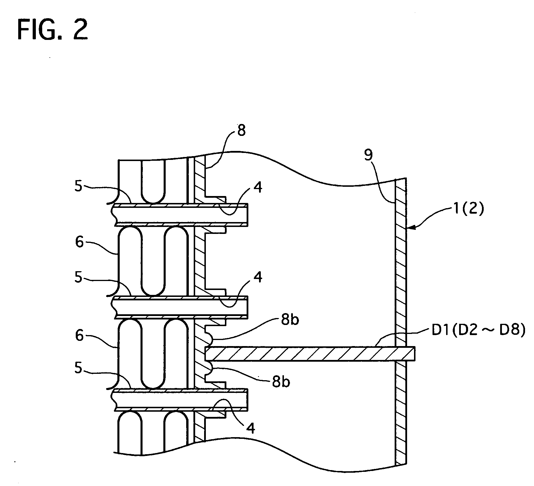
[0011] Therefore, the vertical wall portion ensures firm fixing of the tank and the connector, and the slope wall portion also ensures the fixing by deforming the part of the burring portion to form the inserted projecting portion, where it is deformed easily into the bottom of the holding groove so as to be inserted into the bottom of the holding groove along the vertical wall portion and extend along the slope wall portion the axial direction of the connecting hole for increasing its axial strength.
[0015] Therefore, this can prevent concentration of stress in the root portion of the burring portion when the burring portion is fixed into the connector.

Problems solved by technology

The above known conventional condenser, however, encounters such the following problem.
The temporarily fixed burring portion of the tank and the inner surface of the connecting hole of the connector cause looseness therebetween at times. In addition, looseness also occurs at times between the burring portion of the tank and the inner surface of the connector due to a thermal expansion difference therebetween in the blazing process.
The looseness causes undesirable fixing by blazing.

Method used


Image

  • Condenser
  • Condenser
  • Condenser

Examples


Embodiment Construction

[0038] Throughout the following detailed description, similar reference characters and numbers refer to similar elements in all figures of the drawings.

[0039] A condenser of an embodiment according to the present invention will be described with reference to the accompanying drawings.

[0040] A condenser 100 is used for an air conditioning system and mounted on a front portion of a not-shown vehicle body of a motor vehicle. In this description, terms “left” and “right” are used with respect to the vehicle body, not corresponding to those in the drawings.

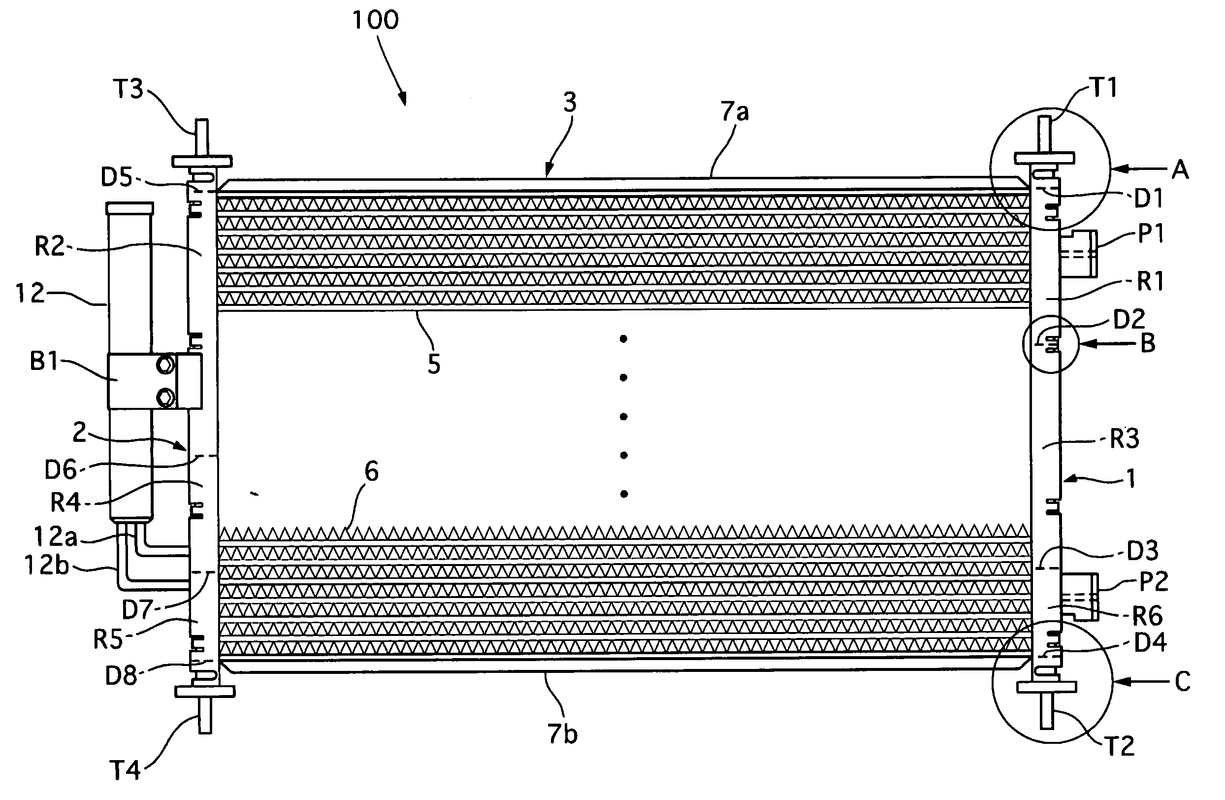
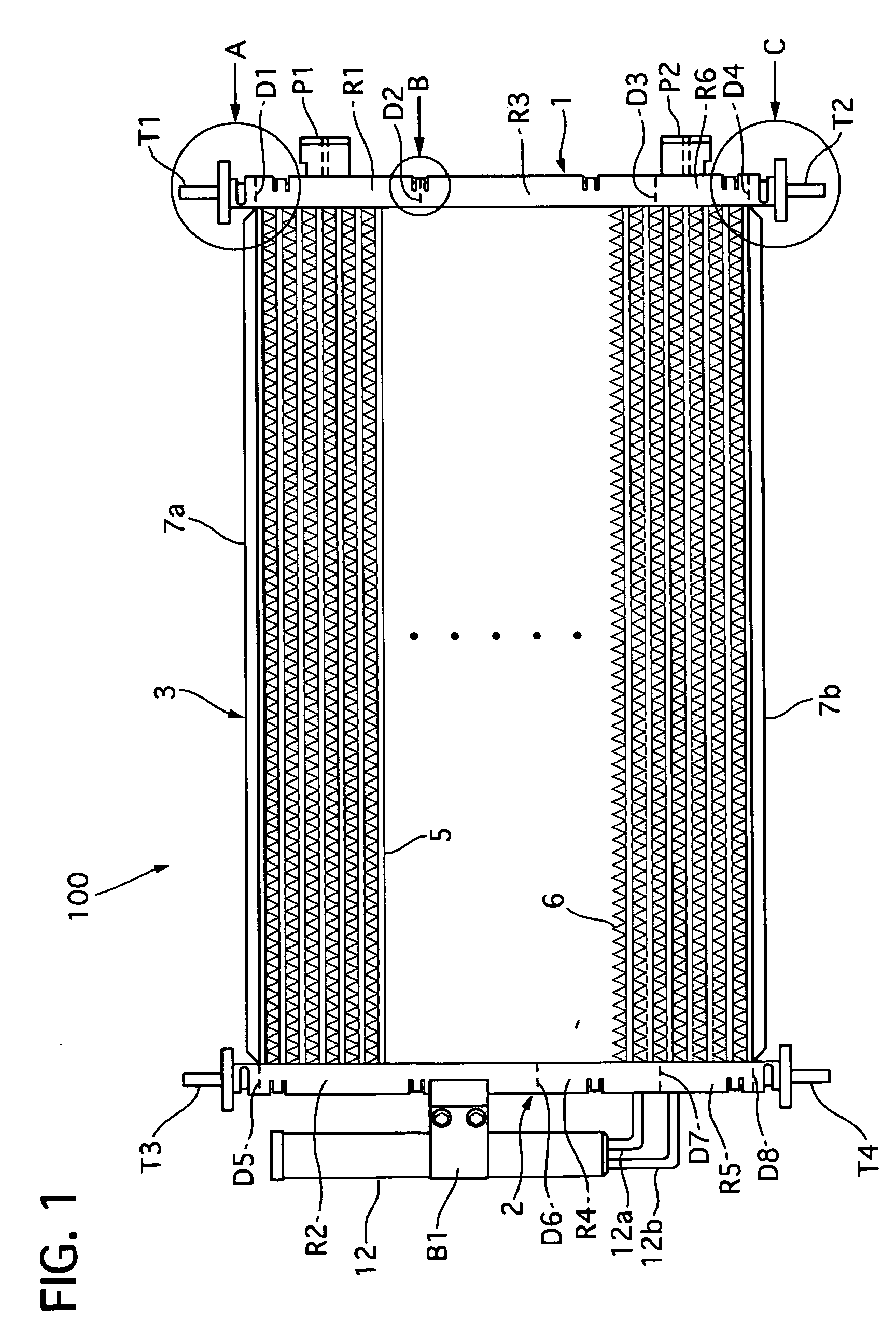
[0041] As shown in FIG. 1, the condenser 100 includes a pair of tanks consisting of a left tank 1 and a right tank 2 that are arranged apart from each other in a lateral direction of the vehicle body and a condenser core 3 that is arranged between the left and right tanks 1 and 2 for cooling refrigerant flowing therethrough.

[0042] The condenser core 3 has a plurality of tubes 5 for flowing the refrigerant therethrough from one of t...


PUM

PropertyMeasurementUnit
Depthaaaaaaaaaa

Abstract

A condenser includes a pair of tanks, at least one of the tanks having a communicating hole, a condenser core arranged between the tanks and having fins and tubes fluidically connected with the tanks, and a connector having a connecting hole. A peripheral portion of the communicating hole is pressed into the connecting hole to form a burring portion which is caulked on an inner face forming the connecting hole so that the connector and the tank are temporarily fixed with each other, and facing portions of the tank and the connector are integrally fixed with each other by blazing. The inner surface of the connecting hole is provided with a holding groove to receive an inserted projecting portion formed on a part of an outer surface of the burring portion for holding the connector to the tank.

Description

BACKGROUND OF THE INVENTION [0001] 1. Field of the Invention [0002] The present invention relates to a condenser which has a tank fixed with a connector by caulking and brazing. [0003] 2. Description of the Related Art [0004] A conventional condenser of this kind is disclosed in Japanese Patent laid-open publication No. 2004-219027. The conventional condenser includes a pair of tanks and a condenser core having a plurality of tubes and fins and arranged between the tanks. One of the tanks is fixed at its top portion with an inlet connector for connecting a pipe, and the other thereof is fixed at its bottom portion with an outlet connector for connecting a pipe. Specifically, the tanks are formed with a communicating hole and the connectors are formed with a connecting hole, so that they can be fluidically communicated with each other. [0005] The connectors are fixed to the tanks, respectively, by caulking and brazing as follows. The tank and the connector are arranged so that the co...

Claims


Application Information

Patent Timeline
IPC IPC(8): F25B39/04F28F9/02B23P15/26B21D53/00
CPCF25B2339/0441F28D1/05366F28D2021/0084F28F9/0212Y10T29/49373F28F9/0246F28F9/0251F28F2220/00F28F9/0224
Inventor YAMAZAKI, HIDEKAZUSHINHAMA, MASAYOSHITSUCHIYA, MINORUMAKISHIMA, YASUHITO
Owner CALSONIC KANSEI CORP
Learn More