Rail clip

Active Publication Date: 2007-03-22
PROGRESS RAIL SERVICES
View PDF2 Cites 4 Cited by
  • Summary
  • Abstract
  • Description
  • Claims
  • Application Information

AI Technical Summary

Benefits of technology

[0011] This invention eliminates the problem of rotation by shaping the top of the clip base so that the front contacts the top arcs of the K slot towards the outer sides which have an inclination of approximately 45° and line contact backwards toward the slot opening is achieved. As the front of the base is forced upwards it wedges itself into the top surface of the K slot & because of the line contact at the sides it resists rotational movement in a similar manner to a spanner on a nut.
[0012] Since there are still large numbers of K plates remaining in service this new invention provides a way to reduce track maintenance costs while they are still used. This invention can also be used for support shoulders in concrete ties that have a similar slot to the K plate.
[0014] One of the disadvantages of the DE clip is that when it is applied to the K plate and equivalent shoulders for concrete ties the clip must be first started in the shoulder by using a special tool which squeezes the toes sidewards so that they can be entered into the vertical slot. Then a second action by another tool or machine is required to drive it onto the rail. The clip of this invention can be driven onto the rail without using a side squeeze tool first which saves time and labour.

Problems solved by technology

During installation of DE clips the application force may only be applied to one leg of the clip resulting in damage to the clip.

Method used


Image

  • Rail clip
  • Rail clip
  • Rail clip

Examples


Embodiment Construction

[0016] A preferred embodiment of the invention will be described with reference to the drawings in which:

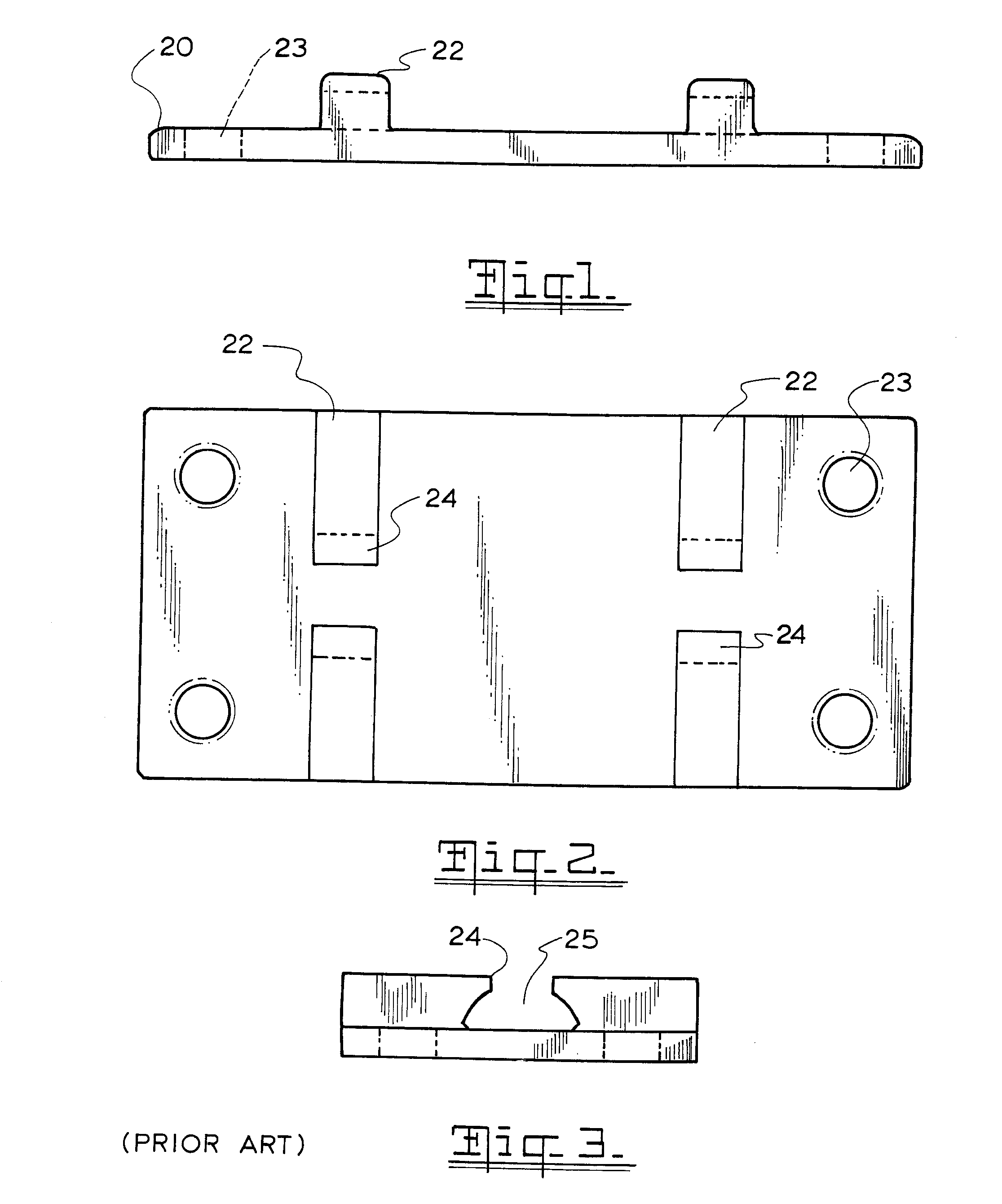
[0017]FIG. 1 is a side elevation of a typical K plate;

[0018]FIG. 2 is a plan view of a K plate;

[0019]FIG. 3 is an end view of a K plate showing the slot with curved upper surfaces which retain the tee bolt;

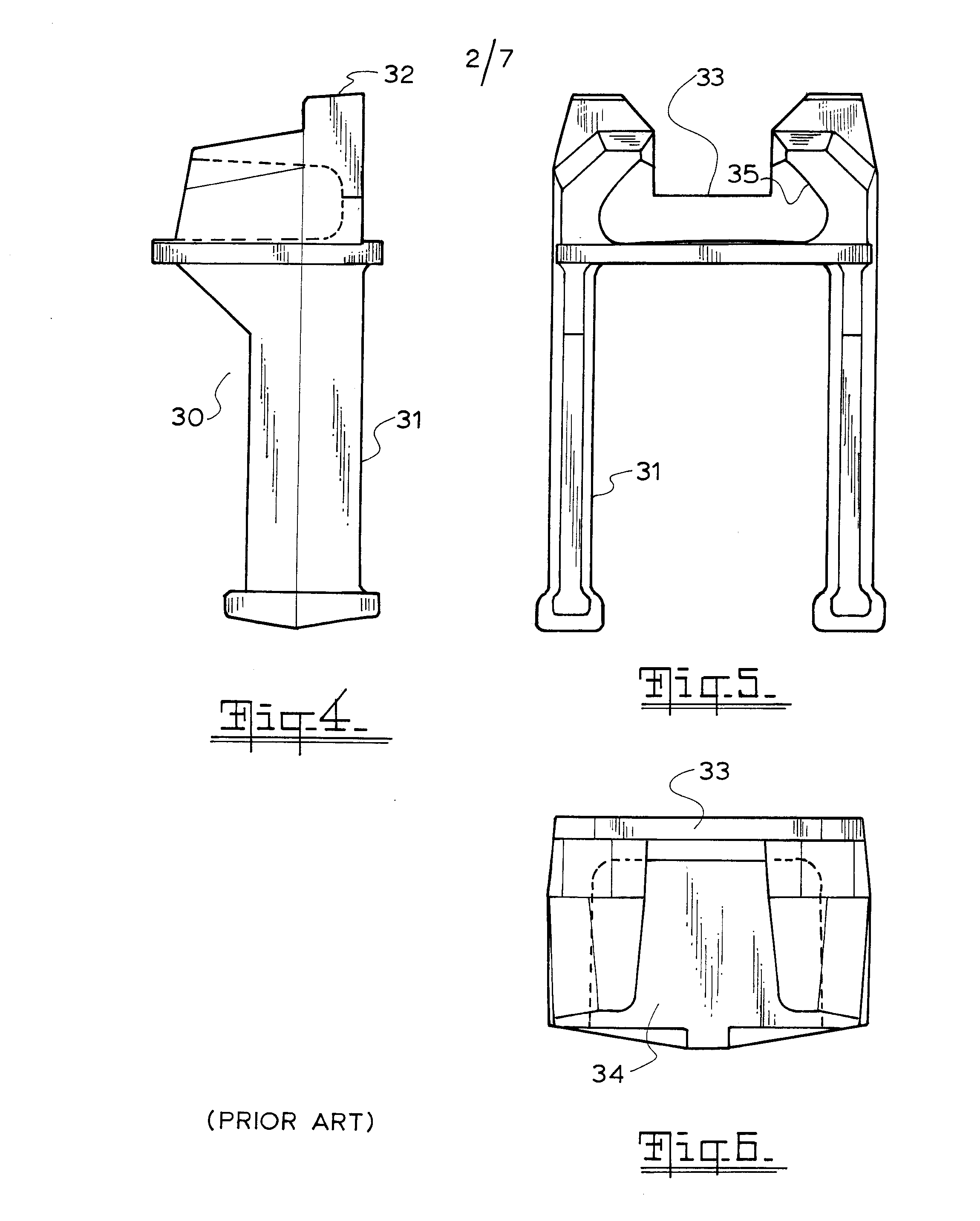
[0020]FIG. 4 is a side elevation of a cast metal shoulder with a clip slot similar to the one in a K plate;

[0021]FIG. 5 is an end elevation of a cast metal shoulder with a clip slot similar to the one in a K plate;

[0022]FIG. 6 is a plan view of a cast metal shoulder with a clip slot similar to the one in a K plate;

[0023]FIG. 7 is plan view of the fastener of this invention in a K plate;

[0024]FIG. 8 is a side elevation of the fastener of this invention in a K plate;

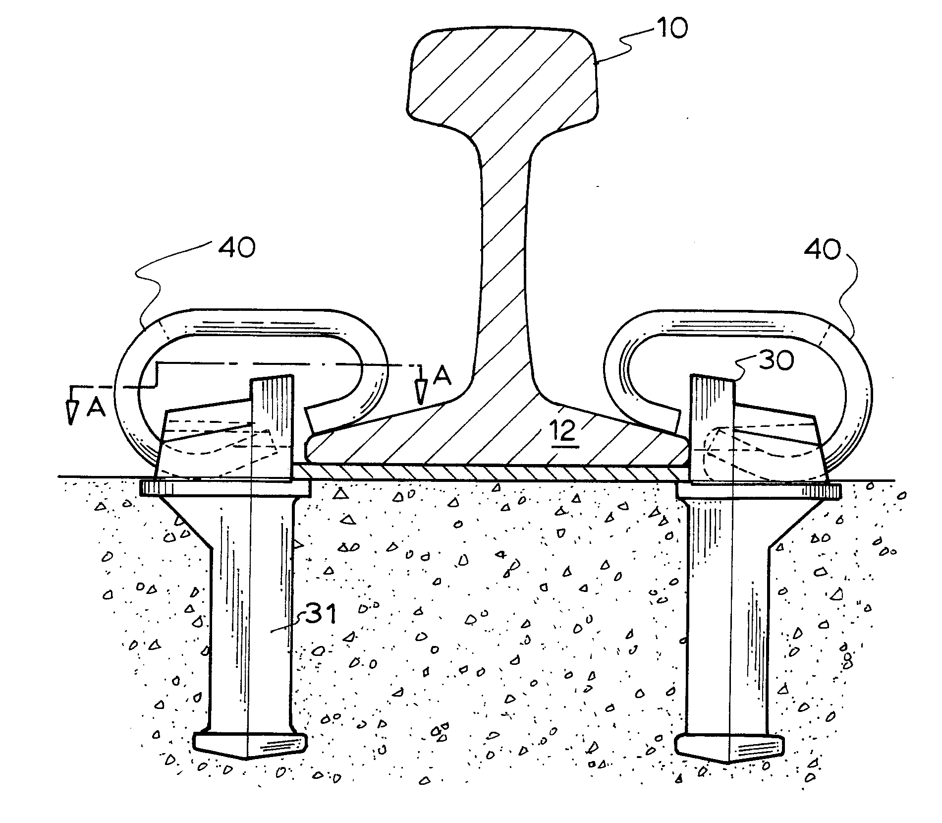
[0025]FIG. 9 is a side elevation of the fastener of this invention on a concrete tie having cast metal shoulders with slots similar to those in a K plate;

[0026]FIG. 10 is a plan view of the fastener of this ...


PUM


Abstract

A rail fastening clip used with a rail clip support having a rail clip slot of the kind used in K plates is disclosed. The rail clip is formed from a U shaped member made of metal plate having a base and two arms tapered from the base to their tips, with the arms being bent inwardly beyond the base in a large arc and the tips are bent back toward the base and oriented for contact with the foot of the rail. The base is adapted to fit in the K plate slot of the rail clip support. The base of said clip has a leading edge remote from the arms that contacts the upper interior surface of the support slot to form at least a line of contact with said upper interior surface of said slot. The line of contact is about 6 mm. The design overcomes the problem of rotation of the clip within the support slot and is a more cost effective clip than that currently used with K plates.

Description

[0001] This invention relates to an improved rail fastener adapted to be used with existing rail plates on wooden rail ties or equivalent support shoulders in concrete ties. BACKGROUND TO THE INVENTION [0002] Dog spikes have been used to hold rails down to wooden railway sleepers for a very long time and in some places they are still used. While they are cheap and simple they do not provide longitudinal restraint to the rail and additional rail anchors must be used for this. [0003] In Europe an upgraded method of clamping the rail to the tie came into use which was made up of a steel plate (commonly called a K plate) under each rail and the plate was attached to the tie by the means of screw spikes. The rail in turn was clamped to the K. plate by means of two tee bolts in each plate which acted upon 2 clamps holding the rail down when the nuts on the captive tee bolts were tightened. However in spite of large spring washers underneath the nuts on the tee bolts they tended to work lo...

Claims


Application Information

Patent Timeline
IPC IPC(8): E01B9/38
CPCE01B9/306
Inventor YOUNG, HARTLEY FRANK
Owner PROGRESS RAIL SERVICES
Why Eureka
Try Eureka