Self Disinfecting Drain Trap

Inactive Publication Date: 2012-10-25
CHABALA MWELWA CHABBY
View PDF5 Cites 2 Cited by
  • Summary
  • Abstract
  • Description
  • Claims
  • Application Information

AI Technical Summary

Benefits of technology

[0016]It is appreciated therefore that use of the invention enables a solid disinfectant tablet, which may be a powder, gel, compressed granules, or liquid contained in a tablet, to be placed in the opening of the branch, by removing the closure cap, without liquid leaking from the trap, because the level of liquid is such that the water barrier is maintained throughout replacement of the disinfectant.
[0036]Ideally the tablet is dimensioned and arranged to be received in the reusable tablet holder. The tablets may be spherical, cone shaped, cuboid or manufactured in any other shape so as to fit inside the reusable tablet holder. Likewise the tablet may be shaped so as to enhance controllable dissolution, for example by having a hollow bore so that water comes into contact with its interior and dissolves the tablet from its inside surface outwards.

Problems solved by technology

Over a period of time the build up of deposits results in build up of bacteria and odours emanating from the drains.
This results in rapid return of bacteria and odours.
In places where there are many such sinks and drains, such as large offices, schools, hospitals and the like, the chance of bacteria spreading from sink, via a drain, to another sink presents a real hazard to health as many diseases are water borne.
Disinfectants poured down a sink, so as to clean a U-bend, tend to get washed away or diluted in a short time and so as they do not dwell in the U-bend for very long, their effectiveness is reduced.
The washing away as water is drained out of a sink results at best therefore results in a weaker concentration of disinfectant.
There are several drawbacks associated with this arrangement.
Thus the seal is prone to leaks.
Also, because the hemispherical container has to be removed periodically to replace the disinfectant, the connecting seal can become worn or contaminated.
A further inconvenience of the hemispherical container being located at the bottom of the U-bend trap arises when it must be removed to replace the disinfectant.
There is also bacteria and debris that tends to be present in such water and this presents in itself a health hazard to the person replacing the disinfectant block.
Furthermore when the water barrier is removed the user is subjected to unpleasant smells, as the barrier between the user and the drain / sewer is removed.
This device suffers from the same drawbacks as does the device of U.S. Pat. No. 644,142, namely that when replacing the disinfectant block, the water barrier is removed so increasing the risk of transmitting bacteria.
In particular, the seal between the removable trap and the pipe loop is below the normal water level of the U-bend, making it prone to leaks.
Food or other detritus from the basin, which settles at the bottom a drain trap U-bend, is usually unsightly.

Method used


Image

  • Self Disinfecting Drain Trap
  • Self Disinfecting Drain Trap
  • Self Disinfecting Drain Trap

Examples


Embodiment Construction

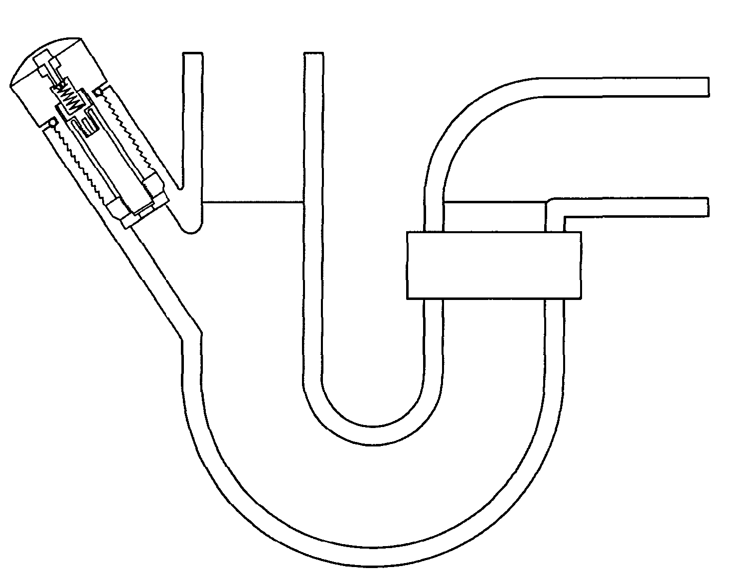
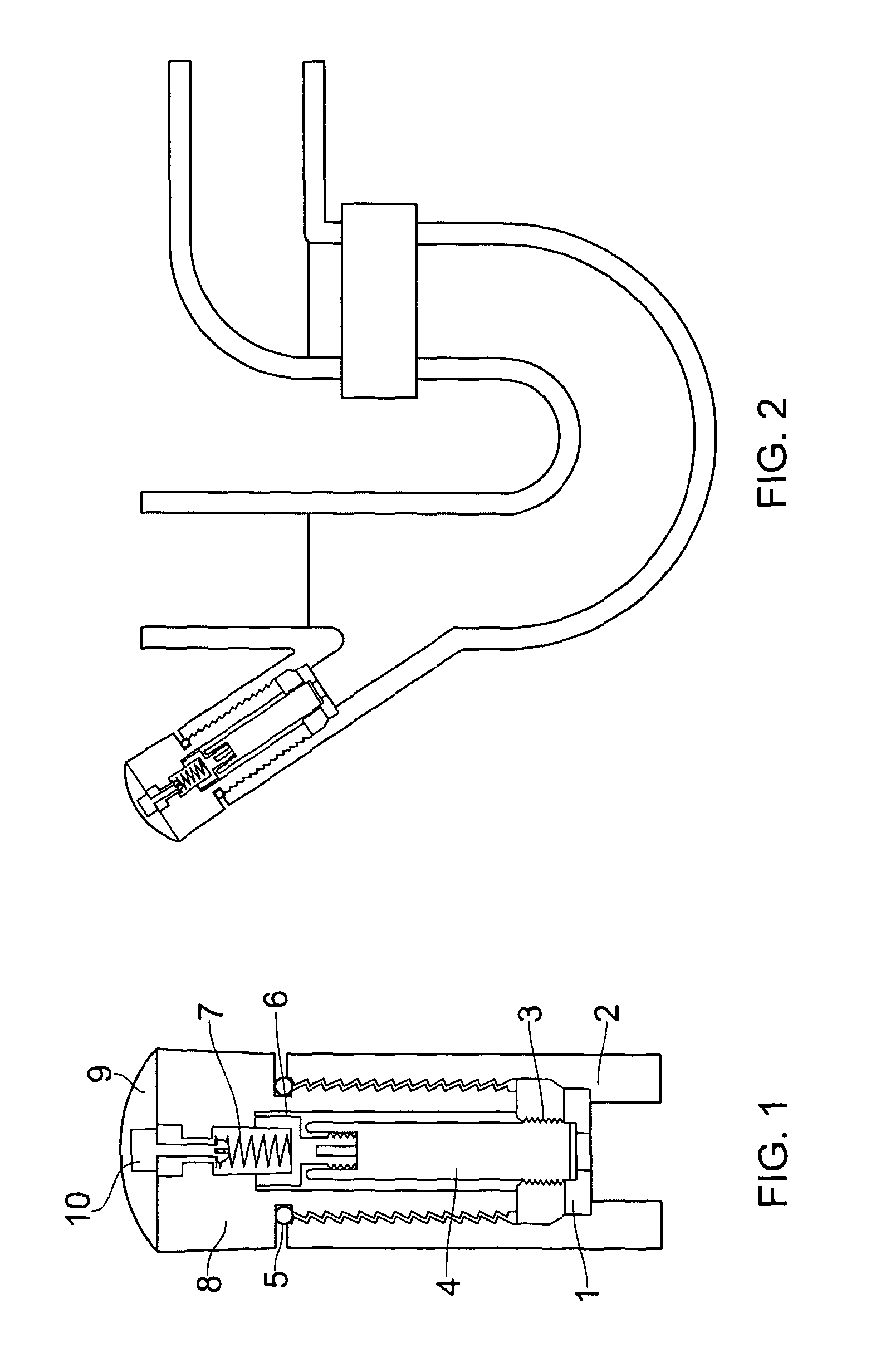
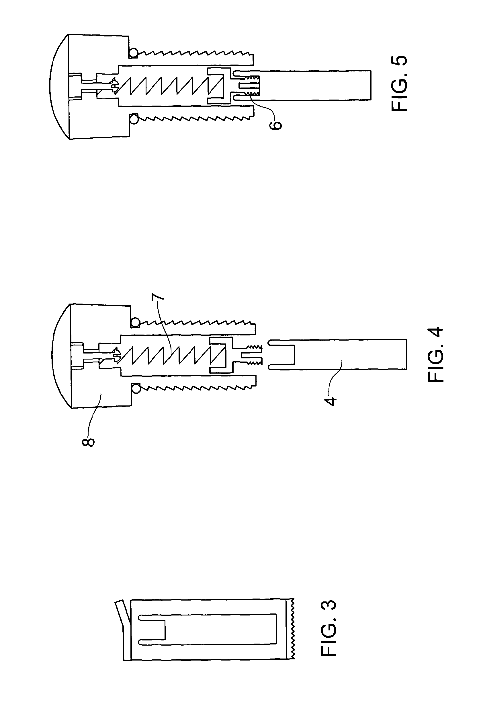
[0049]Referring to FIGS. 1 to 10, in which like parts bear the same reference numerals, there is shown a general assembly of a consumable tablet 40 in a reusable tablet holder 80 to be received in a branch 25 of a U-bend drain or moulding 20. In use a portion of the consumable tablet is in contact with the water in U-bend moulding 20. A closure cap 35 covers the opening of the branch 25.

[0050]A tablet stopper 10 locates the portion of the consumable tablet 40 just below the water level 180, advantageously controlling the rate that the consumable tablet 40 dissolves. This controlled release of disinfectant from the consumable tablet 40 into the water ensures that a continuous disinfectant presence is in the water. A water inlet hole or aperture 120 is optionally provided in the tablet stopper 10 and forms a passage for water to reach the consumable tablet 40.

[0051]In an alternative embodiment a very tiny hole 120 or holes in the stopper 10 can allow or gel disinfectant to drain slowl...


PUM


Abstract

A drain trap U-bend which includes a moulded housing for a re-usable disinfecting tablet dispenser (FIG. 1). The disinfecting tablet dispenser contains a disinfecting tablet (FIG. 4), which is released into the U-bend moulding (FIG. 6: showing the tablet inside the housing moulding) by a spring loaded tension device (FIG. 9: Showing the whole device including u bend, housing, rubber spur, and indicator). The tablet is stabilised within the housing of the dispenser by twin toothed rubber seals. (FIG. 10: Showing the sealant mechanism and that the water level is at the bottom sealer and with additional sealer higher up insuring no infections). The tablet is held in place by an upper ribbed rubber spur (FIG. 5). The dispenser is made water-tight by rubber O-ring that deforms to seal the branch between the dispenser and the moulded housing of the U-bend.

Description

BACKGROUND[0001]This invention relates to self disinfecting drain traps, more particularly it relates to self disinfecting drain traps for improving the standard of hygiene in sinks, baths, lavatories (WCs), showers and like appliances or devices with drains or water traps fitted with U-bends.[0002]U-bends ensure that a barrier of water helps seal drains of sinks, baths, lavatories (WCs), showers and like appliances from main drains and sewers, so reducing odours.PRIOR ART[0003]As waste water that has been used by consumers and industrial users passes through drains and flushes through a U-bend of a sink, and into a drain, it is normal for deposits and sediments in the water to gather in certain sections. Over a period of time the build up of deposits results in build up of bacteria and odours emanating from the drains.[0004]The most notorious section of the drain is the ‘drain trap U bend’ section. The shape of the drain trap U bend is responsible for the rapid build up of bacteria...

Claims


Application Information

Patent Timeline
IPC IPC(8): E03C1/12
CPCE03C1/126C02F1/687Y10T137/0441
Inventor CHABALA, MWELWA CHABBY
Owner CHABALA MWELWA CHABBY
Why Eureka
Try Eureka