Optical flow meter for measuring gases and liquids in pipelines

a flow meter and optical technology, applied in the field of optical flow meter for measuring gases and liquids in pipelines, can solve the problems of low detection efficiency, low operating pressure and flow rate, and low accuracy performance, so as to reduce beam convergence, widen the focal spot, and maximize the contrast of detected scattered light

Active Publication Date: 2007-03-22
PHOTON CONTROL INC
View PDF16 Cites 10 Cited by
  • Summary
  • Abstract
  • Description
  • Claims
  • Application Information

AI Technical Summary

Benefits of technology

[0022] Means are also provided to block the unscattered light using an opaque obscuration positioned to intercept the beams at or behind the second window to prevent the unscattered light from reaching the detector. The obscuration is sized to block most or all of the unscattered light, but is smaller than the aperture of the second window to maximize the contrast of the detected scattered light.
[0023] The first optical system, first window, the second window, opaque obscuration and second optical system are approximately centered on a common optical axis that is approximately perpendicular to the pipe flow d

Problems solved by technology

There are many mechanical methods for determining the flow rate in pipes, including orifice plates, pitot tubes, Venturi meters, vortex meters, coriolis effect meters, variable area meters, and turbine meters, but generally they require that obstructive structures be inserted inside the pipe, which is undesirable in many applications because it disrupts the fluid flow and creates a pressure drop.
This is problematic for some applications where the reservoir pressure is very low, such as coal bed methane production, or when the fluid is vented to atmosphere or a large storage vessel.
Many ultrasound meters require pockets in the pipe walls to seat the ultrasound transducers, which is undesirable because contaminants tend to build up in the cavities.
Long sections of pipe are required to accommodate the ultrasonic beam paths, which can be awkward and expensive, especially for large pipe diameters.
Other versions of ultrasonic flow meters launch the ultrasonic waves through the wall of the pipe, using clamp on transducers, but the accuracy performance suffers at low operating pressures and low flow rates.
This technique is useful when measuring complex flows, where there are many large scattering particles, but because the light is distributed over many intensity maxima, the detection efficiency is low and small particles do not scatter enough light to be measured effectively.
The combination of these effects is very complex and generalized theories such as Mie and Rayleigh scattering fail to predict real world r

Method used


Image

  • Optical flow meter for measuring gases and liquids in pipelines
  • Optical flow meter for measuring gases and liquids in pipelines
  • Optical flow meter for measuring gases and liquids in pipelines

Examples


Embodiment Construction

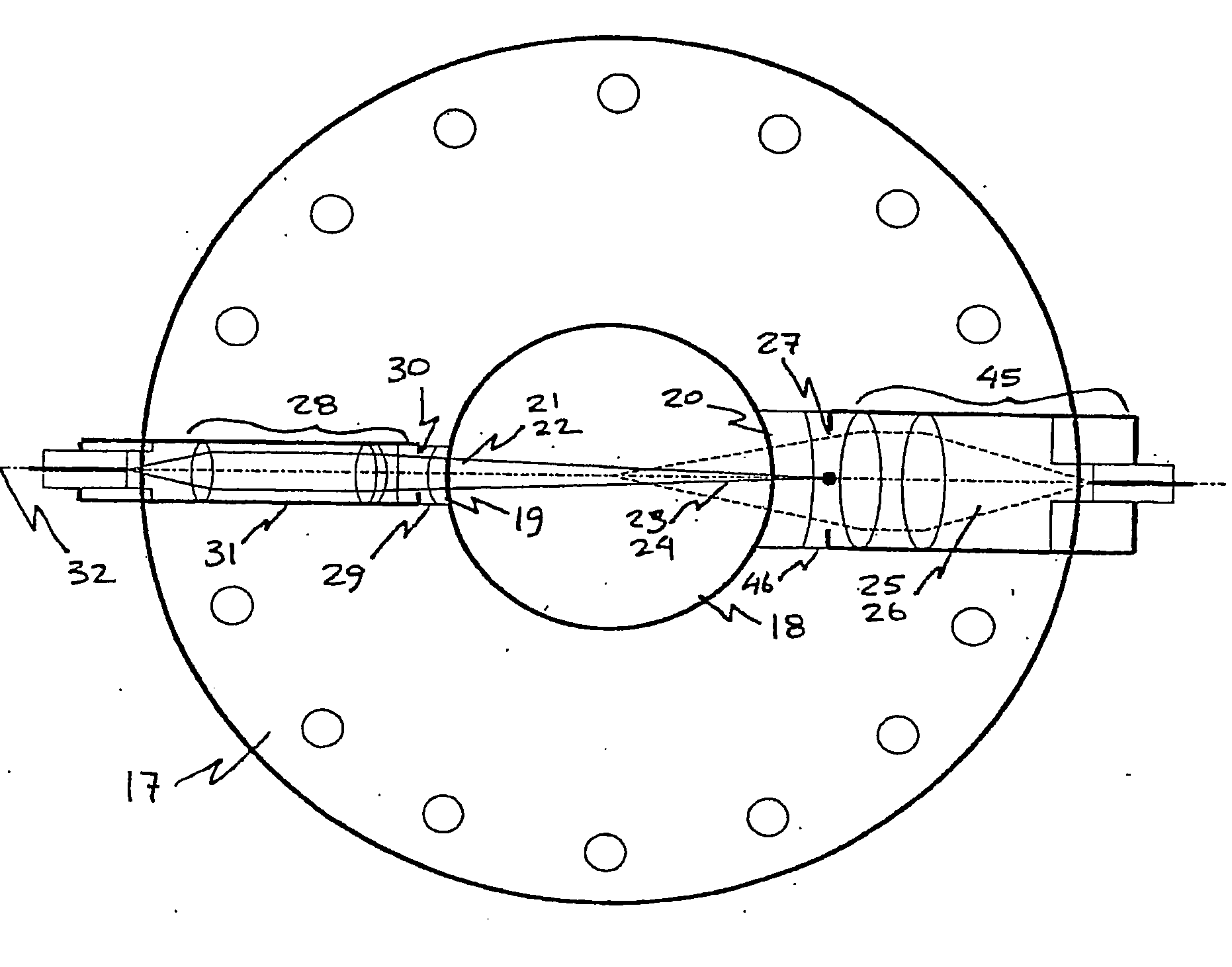
[0038] There is shown in FIG. 3 an optical flow meter constructed in accordance with the preferred embodiment to determine the flow rate of a fluid in a pipe, by measuring the velocity of small particles carried by the fluid stream. The flow meter apparatus is comprised of an opto-mechanical head 10 inserted between adjacent flanges 11 in the pipe 12, an electro-optical assembly 13 which contains two laser light sources 14, two scatter signal photo-detectors 54 and 55, and processing electronics 15, and a fiber-optic extension cable conduit 16 which connects the electro-optical assembly 13 to the opto-mechanical head 10. In this configuration, the electro-optical assembly 13 can be located remotely so that no electrical potentials are present at the opto-mechanical head 10, which is desirable when the fluid passing through the pipe can be ignited by sparks or short circuits, such as natural gas. Furthermore, the fiber-optic terminations at the opto-mechanical head 10 are compact, ro...


PUM


Abstract

An optical system design for measuring the velocity of fluids flowing through pipes or other conduits is disclosed. The optical system is comprised of a means for delivering two beams through a window in the wall of the pipe, focused to two points aligned along an axis of the pipe and separated by a known distance, and means for detecting light that is scattered by particles carried in the fluid stream through a second window, that is disposed on the opposite side of the pipe. By measuring the time delay between detected signals, the velocity of the fluid can be determined. The delivered light beams are focused in a shallow cone of light and are blocked by an obstruction disposed behind the second window. The scattered light passes through an aperture behind the second window that surrounds the obscuration, and is focused on to a detector surface.

Description

BACKGROUND OF THE INVENTION [0001] The present invention generally relates to metering devices for measuring the velocity of fluid flowing in a pipe, and is typically used to determine the flow volume rate in industrial applications, such as the transport of natural gas. More specifically, the invention relates to an optical system that focuses two light beams in the pipe through a transparent window in the pipe wall, and detecting the time of flight delay of light scattered by small particles carried by the fluid, as the particles pass from one focal spot to the other. [0002] In pipeline operations and other industrial processes, flow meters are used to measure the flow rate of gases or fluids moving through the pipeline. There are many mechanical methods for determining the flow rate in pipes, including orifice plates, pitot tubes, Venturi meters, vortex meters, coriolis effect meters, variable area meters, and turbine meters, but generally they require that obstructive structures...

Claims


Application Information

Patent Timeline
IPC IPC(8): G01P3/36G01F1/66G01P5/20
CPCG01F1/661G01F1/662G01P5/20G01N2015/0294G01N15/0205
Inventor MONTGOMERY, DEREKJAMES, DARYLYAN, DAVID YUE
Owner PHOTON CONTROL INC
Why Eureka
Try Eureka