
Optical film and surface light source using it

a surface light source and optical film technology, applied in the field of optical film, can solve the problems of holograms being considered improper for bending white light, unable to control the diffusion angle range of microscopic beads or rods, and deteriorating front brightness, so as to achieve uniform light diffusion, reduce brightness, and secure high brightness

Inactive Publication Date: 2007-03-22
HITACHI CHEM CO LTD
View PDF4 Cites 70 Cited by
  • Summary
  • Abstract
  • Description
  • Claims
  • Application Information

AI Technical Summary

Benefits of technology

[0017] In consideration of these circumstances, an object of the present invention is to provide an optical film for controlling a light emitting direction, capable of maintaining high brightness and preventing moire fringes, Newton rings, and brightness unevenness. Also provided is a surface light source employing the optical film.
[0034] Preferably, a film having a function of preventing polarization split, color separation, and reflection is arranged between the light guide and the optical film, or on the exit surface of the optical film. Preferably, arranging a discrete diffuser film is not needed.
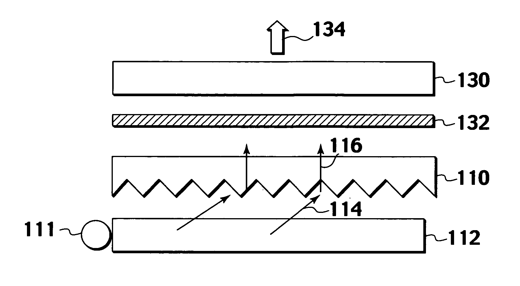
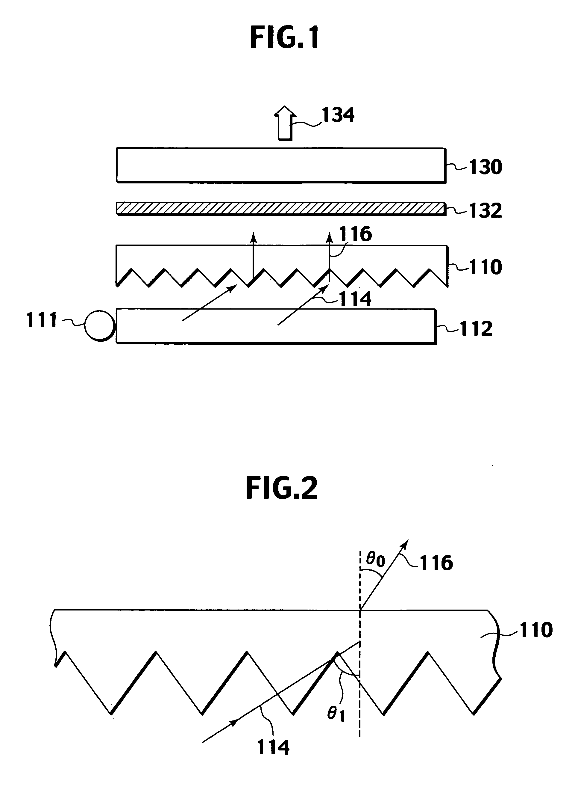
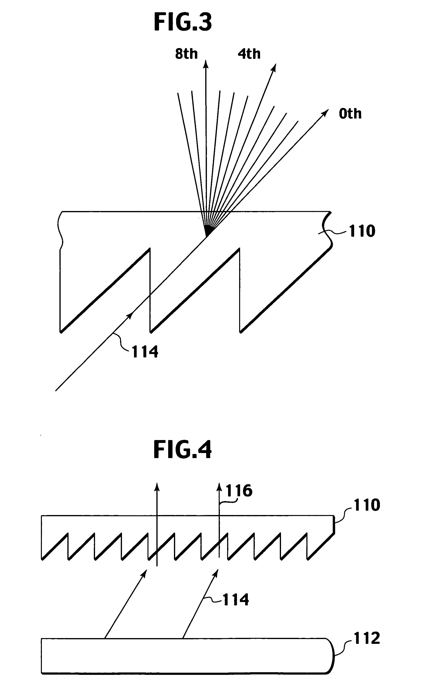
[0036] Preferably, the light guide emits light at an angle close to the exit surface thereof, i.e., at a large output angle, to provide the light with directivity in this direction. The light guide little bends incident light from a light source and emits the light at a large output angle, to thereby secure high brightness.
[0037] Preferably, the light bending material maintains the directivity provided by the light guide and bends the light in a direction perpendicular to the exit surface. Preferably, the diffuser efficiently diffuses light emitted from the material into a narrow diffusing range. With the material making light substantially perpendicularly incident to the diffuser, the diffuser can evenly diffuse the light without decreasing brightness.
[0038] Preferably, the brightness of light emitted from the light guide has a peak in the output angle range of 50° to 80° on the exit surface of the light guide, and a half-value width of the peak is 30° or below. Preferably, the light bending material bends light emitted from the light guide in a direction perpendicular to the exit surface of the light guide while keeping the directivity of the light. Preferably, the diffuser is a vertical deflection diffuser to efficiently diffuse light emitted from the material into a narrower range.

Problems solved by technology

This technique may suppress moire fringes and Newton rings but is unable to control the range of diffusion angles of the microscopic beads or rods.
As a result, light may substantially uniformly diffuse into every direction, to drastically deteriorate front brightness.
The hologram has been considered improper for bending white light because it causes spectral dispersion and high-order diffraction.
It is difficult, however, to align output angles over the surface of the light guide.
Then, brightness unevenness easily occurs.
The diffuser having a limited range of diffusion angles, however, hardly secures a required diffusion characteristic to control a brightness distribution if light is obliquely made incident thereto from the light guide.

Method used


Image

  • Optical film and surface light source using it
  • Optical film and surface light source using it
  • Optical film and surface light source using it

Examples


embodiments

[0094] Embodiments of the present invention will be explained with reference to the drawings. These embodiments are not intended to limit the present invention.

[0095]FIG. 11 is a view showing a configuration of an optical film according to an embodiment of the present invention.

[0096] The optical film 10 has a transparent base film 11. One face of the base film 11 is an incident surface 12 on which a predetermined shape is formed. The other face of the base film 11 is an exit surface 13 on which a hologram is formed.

[0097] The base film 11 is made of, for example, polyethylene terephthalate (PET). The predetermined shape on the incident surface 12 and the hologram on the exit surface 13 are formed from photo-curable resin.

[0098] The base film 11 bends incident white light through the predetermined shape formed on the incident surface 12 and perpendicularly emits the light from the exit surface 13. The hologram formed on the exit surface 13 serves as a diffuser to diffuse the lig...


PUM


Abstract

An optical film 10 has a transparent base film 11 made of polyethylene terephthalate (PET), a prism made of photo-curing resin such as acryl modified epoxy on an incident surface 12 that is one face of the base film 11, and a hologram similarly made of photo-curing resin on an exit surface 13 opposing the incident surface 12. The prism has grooves or ridges each having a substantially triangular cross section to totally reflect incident light so as to bend the light into a direction perpendicular to the exit surface 13. The hologram anisotropically diffuses light exiting from the exit surface 13, to improve brightness.

Description

TECHNICAL FIELD [0001] The present invention relates to an optical film for controlling the direction of outgoing light and a surface light source employing such an optical film. BACKGROUND ART [0002] Liquid crystal displays are used as computer displays, control panels of home appliances, cellular phone displays, and the like. There is an increasing demand for reducing the power consumption, weight, and thickness of the liquid crystal display. The liquid crystal display typically employs a transmissive liquid crystal panel. [0003] The liquid crystal display of this type employs a surface light source as a backlight to illuminate a liquid crystal panel from the back. The surface light source has a light guide to emit areal light based on light from a light source and an optical film to control the direction of outgoing light of the light guide so that as much light as possible is emitted toward the front of an observer who watches the liquid crystal display. [0004]FIG. 1 shows a con...

Claims


Application Information

Patent Timeline
IPC IPC(8): G02B5/32F21S2/00F21V5/00F21V5/02F21V8/00F21Y103/00G02B5/02G02F1/13357
CPCG02B5/0252G02B5/0257G02B5/0278G02B6/0065G02B6/0038G02B6/0053G02B5/32B29D11/00788G02B5/1847
Inventor HOSHINO, TETSUYASUGIMOTO, YASUSHITESHIMA, TERUODOBASHI, TOMO
Owner HITACHI CHEM CO LTD
Learn More