Optical film

a technology of optical film and film film, applied in the field of optical film, can solve the problems of difficult to achieve high luminance, difficult to adopt edge-lit backlights for a large-area liquid crystal panel, compared to direct-lit backlights, etc., and achieve the effect of preventing non-uniform exterior defects and minimizing the visibility of vertex portions

Active Publication Date: 2022-09-13
LMS
View PDF17 Cites 0 Cited by
  • Summary
  • Abstract
  • Description
  • Claims
  • Application Information

AI Technical Summary

Benefits of technology

[0010]Provided is an optical film for minimizing the visibility of vertex portions of a plurality of square pyramid-shaped lenses arranged on the optical film and preventing non-uniform exterior defects.
[0011]Provided is also an optical film for minimizing the luminance loss of light emitted from small-sized light emitting diodes (LEDs) and reducing generation of hot spots by evenly diffusing light.
[0012]Provided is also an optical film for minimizing the luminance loss of light emitted from small-sized LEDs during conversion of the light to white light.

Problems solved by technology

Therefore, it is difficult to adopt edge-lit backlights for a large-area liquid crystal panel, compared to direct-lit backlights.
Moreover, it is difficult to achieve high luminance with the edge-lit backlights in view of supply of light through the light guide plate.

Method used


Image

  • Optical film
  • Optical film
  • Optical film

Examples


Embodiment Construction

[0030]The operation principle of preferred embodiments of the disclosure will be described below in detail with reference to the attached drawings. A detailed description of a generally known function or structure of the disclosure will be avoided lest it should obscure the subject matter of the disclosure. Although the terms used in the present disclosure are defined in consideration of functions in the embodiments of the disclosure, the terms may be changed according to the intention of a user or an operator, or customs. Therefore, the definitions should be made, not simply by the actual terms used but by the meanings of each term lying within.

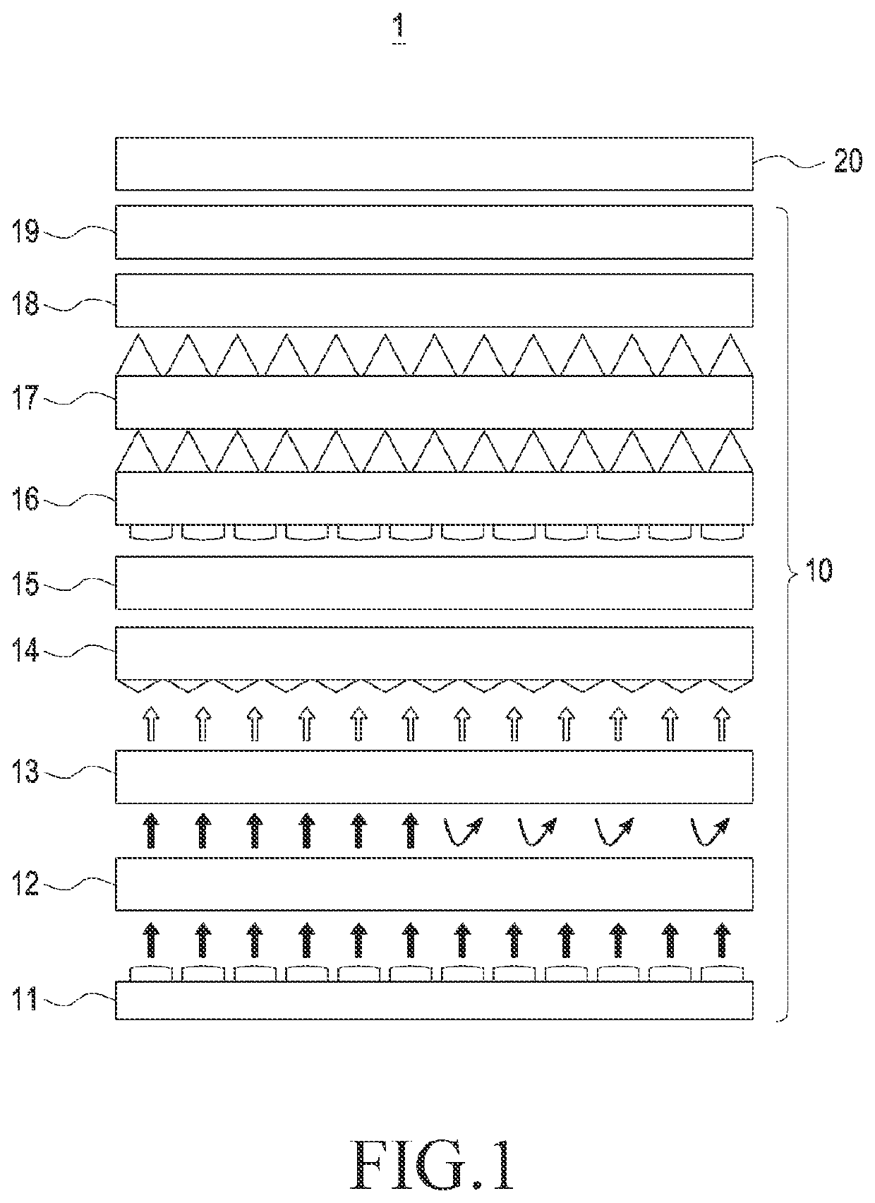
[0031]A backlight unit is a light source for a liquid crystal display (LCD). The LCD does not emit light autonomously. Therefore, a backlight unit with light sources irradiates light toward a liquid crystal panel from the rear surface of the LCD, forming an identifiable image.

[0032]The backlight unit uses cold cathode fluorescent lamps (CCFL...


PUM

PropertyMeasurementUnit
heightsaaaaaaaaaa
sizeaaaaaaaaaa
sizeaaaaaaaaaa

Abstract

An optical film is disclosed. The optical film may include a first base film, and a diffusion lens layer disposed on one surface of the first base film and including a plurality of square pyramid-shaped lenses. Edges meeting at vertices of the plurality of square pyramid-shaped lenses may be curved lines. Among the plurality of square pyramid-shaped lenses, one surface of a first square pyramid-shaped lens may meet one surface of a second square pyramid-shaped lens to form a boundary line, and the one surface of the first square pyramid-shaped lens and the one surface of the second square pyramid-shaped lens may be symmetrical with respect to the boundary line as an axis.

Description

CROSS-REFERENCE TO RELATED APPLICATION(S)[0001]This application is based on and claims priority under 35 U.S.C. § 119 to Korean Patent Application No. 10-2020-0105107, filed on Aug. 21, 2020, in the Korean Intellectual Property Office, the disclosure of which is incorporated by reference herein in its entirety.BACKGROUNDField[0002]The disclosure relates to an optical film, and more particularly, to an optical film that splits and diffuses light emitted from a light source.Description of Related Art[0003]Backlights are generally classified into an edge type and a direct type according to the locations of the backlights.[0004]Edge-lit backlights are located along the edges of a liquid crystal panel and emit light to the liquid crystal panel through a light guide plate. Therefore, it is difficult to adopt edge-lit backlights for a large-area liquid crystal panel, compared to direct-lit backlights. Moreover, it is difficult to achieve high luminance with the edge-lit backlights in view ...

Claims


Application Information

Patent Timeline
Patent Type & Authority Patents(United States)
IPC IPC(8): G02B5/02F21V5/00G02F1/13357G02B1/04G02B3/00
CPCG02B5/0221F21V5/004G02B1/041G02F1/133603G02F1/133606G02B2003/0093G02F1/133611G02F1/133607G02F1/133614G02B5/0231G02B5/206G02B6/0051G02B6/0073G02B6/0055G02B5/0215G02B5/20G02F1/133504G02F1/133514G02F1/133553
Inventor KIM, JINHWANLEE, TAEJUNKIM, HYERYONGLEE, JIHOONYOON, SEONGYONGKIM, JITAE
Owner LMS
Why Eureka
Try Eureka