Image processing apparatus and method

a technology of image processing and apparatus, applied in the field of image processing apparatus and method, can solve the problems of low albedo, inability to obtain variable, and inability to completely remove the influence caused by illumination variation

Active Publication Date: 2007-03-22
KK TOSHIBA
View PDF10 Cites 30 Cited by
  • Summary
  • Abstract
  • Description
  • Claims
  • Application Information

AI Technical Summary

Benefits of technology

[0015] According to embodiments of the present invention, an image processing apparatus comprises: a weight calculation unit configured to calculate a weight of a weighted smoothing filter, a first filter unit configured to generate a smoothed image by applying the weighted smoothing filter to the input image, and a second filter unit configured to obtain the feature image by dividing a pixel value of the input image by a pixel value of the smoothed image, wherein the weight calculation unit includes (1) a diffuse reflection image generation unit configured to generate a diffuse reflection image by using a model having a diffuse reflection component as a main component, the diffuse reflection image approximating the input image, and (2) a difference image generation unit configured to generate a difference image between the diffuse reflection image and the input image, and the weight calculation unit evaluates a difference value between pixel values of each noted pixel and its surrounding pixel in the difference image, and assigns to the surrounding pixel a weight that decreases with increase of the difference value.

Problems solved by technology

However, in the case where the lighting condition varies in the local area, mainly in the case where a shadow is formed, the invariance can not be obtained, and erroneous recognition or identification is caused.
However, since the lighting conditions in the shadow areas are different from those in other areas, it is impossible to completely remove the influence caused by illumination variations, as schematically indicated in the face image 502.
However, in the binarization, there is a possibility that an area with a low albedo (for example, in the case of the face image recognition, a pupil or an eyebrow) is also erroneously detected as a shadow area.
Besides, in an area where a pixel value is gradually changed like a soft shadow formed in a contour portion of a shadow area, since it is difficult to set a suitable threshold, an irregular or improper recognition would occur in the binarization technique.
Further, in an area where for example, specular reflection occurs and a reflection component varies, since it is difficult to extract a value of a diffuse reflection component from only the one given input image, the invariance can not be calculated in the conventional method.

Method used


Image

  • Image processing apparatus and method
  • Image processing apparatus and method
  • Image processing apparatus and method

Examples


first embodiment

[0030] The object recognition apparatus 100 of the first embodiment will be described with reference to FIGS. 1, 2, 6 and 7.

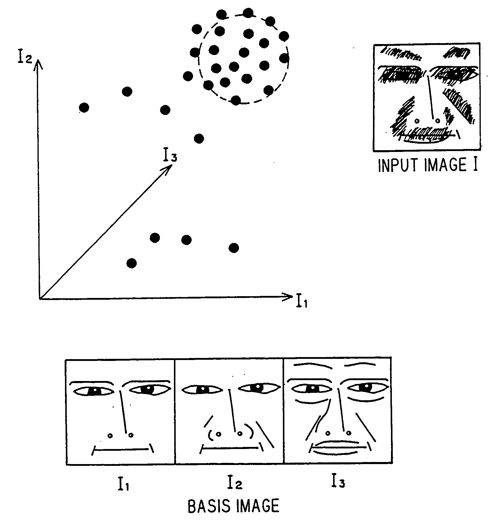
[0031] In this embodiment, the weight to be assigned to the weighted Gaussian filter is calculated by using a face model.

(1) Structure of the Object Recognition Apparatus 100

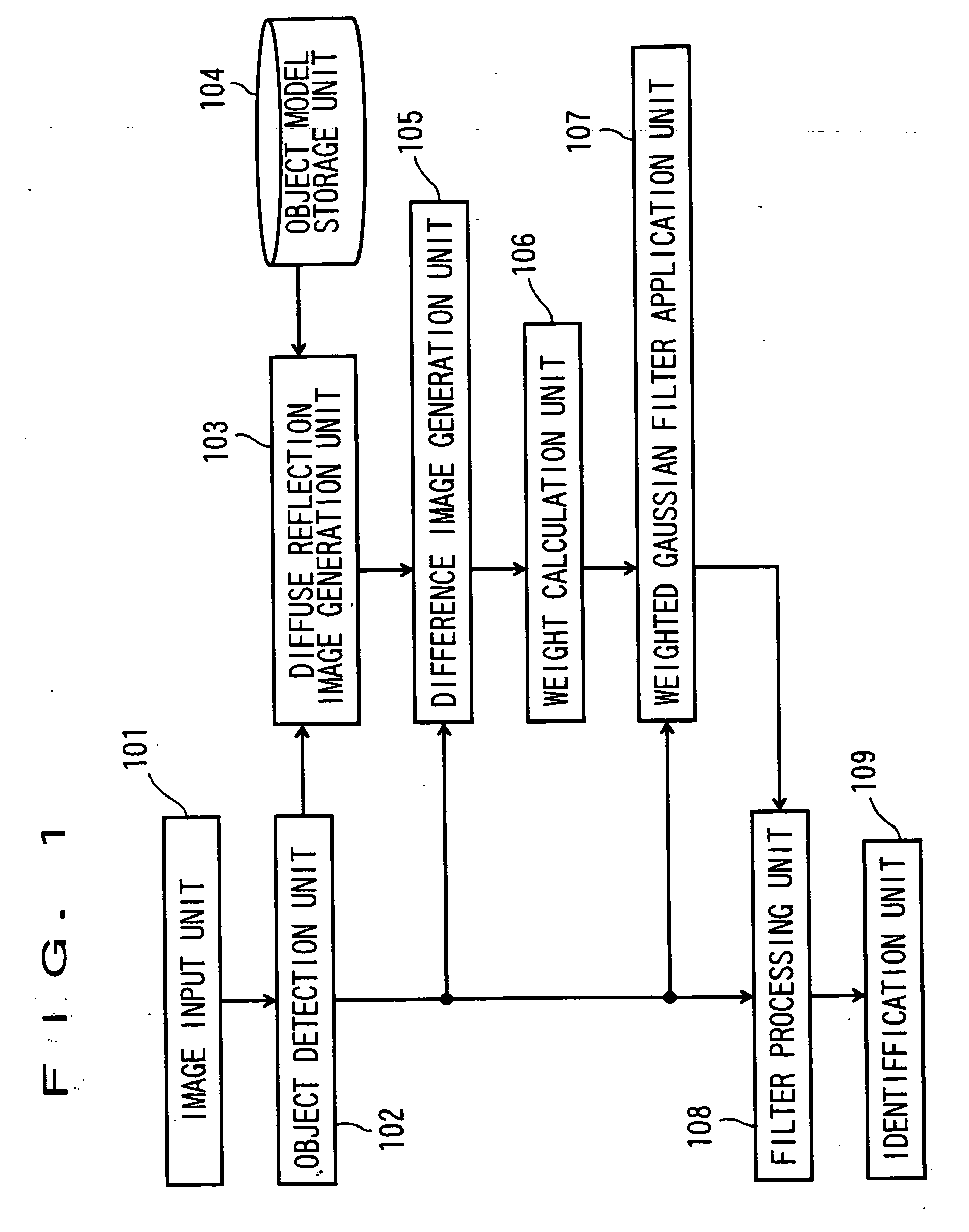
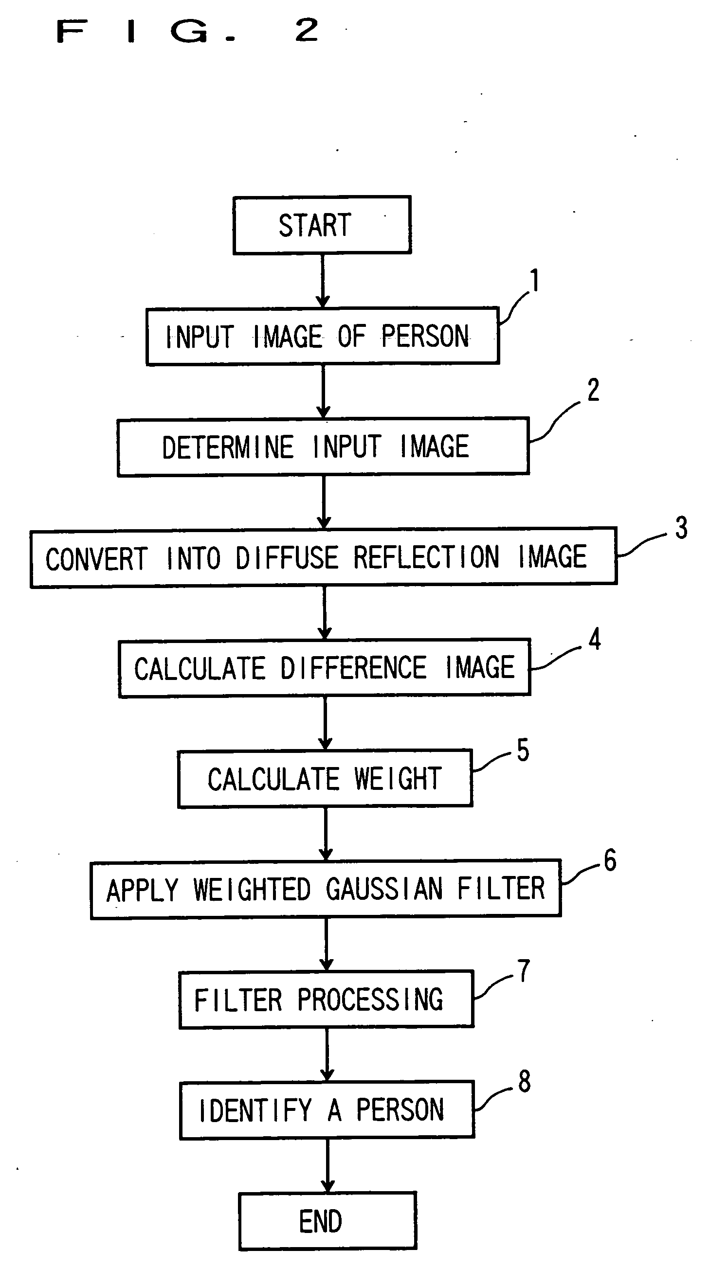
[0032]FIG. 1 shows the structure of the object recognition apparatus 100, and FIG. 2 shows a flowchart of its processing.

[0033] The object recognition apparatus 100 includes an image input unit 101, an object detection unit 102, a diffuse reflection image generation unit 103, an object model storage unit 104, a difference image generation unit 105, a weight calculation unit 106, a weighted Gaussian filter application unit 107, a filter processing unit 108, and an identification unit 109. The function of each of the units 101 to 109 may be realized by a program stored in a computer.

(2) Image Input Unit 101

[0034] As indicated in step 1 of FIG. 2, the image input unit 101 takes an image ...

second embodiment

[0063] The object recognition apparatus 200 of the second embodiment will be described with reference to FIG. 3.

(1) Structure of the Object Recognition Apparatus 200

[0064]FIG. 3 shows the structure of the object recognition apparatus 200.

[0065] The object recognition apparatus 200 includes an image input unit 201, an object detection unit 202, a diffuse reflection image generation unit 203, an object model storage unit 204, a difference image generation unit 205, a reflection component judgment unit 206, a pixel value replacement unit 207, a difference image correction unit 208, a weight calculation unit 209, a weighted Gaussian filter application unit 210, a filter processing unit 211, and an identification unit 212.

[0066] Incidentally, the image input unit 201 performs the same processing as the image input unit 101; the object detection unit 202, as the object detection unit 102; the diffuse reflection image generation unit 203, as the diffuse reflection image generation unit...

third embodiment

[0074] The object recognition apparatus 300 of the third embodiment will be described with reference to FIG. 4.

[0075]FIG. 4 shows the structure of the object recognition apparatus 300. The object recognition apparatus 300 includes an image input unit 301, an object detection unit 302, an object model selection unit 303, an object model storage unit 204, a diffuse reflection image generation unit 305, a difference image generation unit 306, a weight calculation unit 307, a weighted Gaussian filter application unit 308, a filter processing unit 309, and an identification unit 310.

[0076] The image input unit 301 performs the same processing as the image input unit 101 in FIG. 1; and the object detection unit 302, as the object detection unit 102 in FIG. 1.

[0077] The object model selection unit 303 estimates the face direction of a face image outputted from the object detection unit 302, and selects a suitable model from plural diffuse reflection image generation models stored in the...


PUM


Abstract

An object recognition apparatus in an embodiment includes an image input unit, an object detection unit, a diffuse reflection image generation unit, an object model storage unit, a difference image generation unit, a weight calculation unit, a weighted Gaussian filter application unit, a filter processing unit, and an identification unit. A weight to be assigned to a weighted Gaussian filter is determined in view of variations in lighting conditions and reflection components of pixels of an input image.

Description

CROSSREFERENCE TO RELATED APPLICATIONS [0001] This application is based upon and claims the benefit of priority from the prior Japanese Patent Application No. 2005-259895, filed on Sep. 5, 2005; the entire contents of which are incorporated herein by reference. FIELD OF THE INVENTION [0002] The present invention relates to an image processing apparatus and method which raises accuracy of image processing by removing the influence caused by illumination from an image having an object to be recognized, and by extracting a feature intrinsic to the object. DESCRIPTION OF THE BACKGROUND [0003] When to make recognition of an object from the image, it is necessary to minimize the influence caused by illumination variation which would decrease success rate of the recognition. For this purpose, in WANG (Haitao Wang, Stan Z. Li, Yangsheng Wang, Generalized Quotient Image, Proceedings IEEE Conference on Computer Vision and Pattern Recognition, vol. 2, (2004) 498-505), there is proposed a metho...

Claims


Application Information

Patent Timeline
Patent Type & Authority Applications(United States)
IPC IPC(8): G06K9/46G06K9/40G06V10/60
CPCG06K9/00208G06K9/4661G06K9/00221G06V20/647G06V40/16G06V10/60
Inventor NISHIYAMA, MASASHIYAMAGUCHI, OSAMU
Owner KK TOSHIBA
Why Eureka
Try Eureka