Printer, cut paper discharge mechanism used for printer, and paper jam prevention method

Inactive Publication Date: 2007-03-22
NEC PLATFORMS LTD
View PDF14 Cites 14 Cited by
  • Summary
  • Abstract
  • Description
  • Claims
  • Application Information

AI Technical Summary

Benefits of technology

[0014] It is an object of the present invention to provide a printer having a function of preventing

Problems solved by technology

A paper jam is problematically caused in a printer in which full-cut papers are discharged to above a discharge mechanism.
However, Patent Documents 1 and 2 fail to disclose an improvement of an arrangement in portions other than the cutt

Method used


Image

  • Printer, cut paper discharge mechanism used for printer, and paper jam prevention method
  • Printer, cut paper discharge mechanism used for printer, and paper jam prevention method
  • Printer, cut paper discharge mechanism used for printer, and paper jam prevention method

Examples


Example

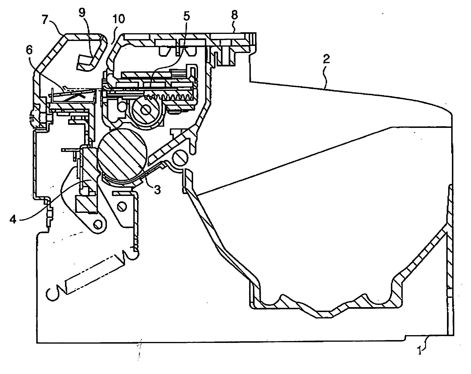
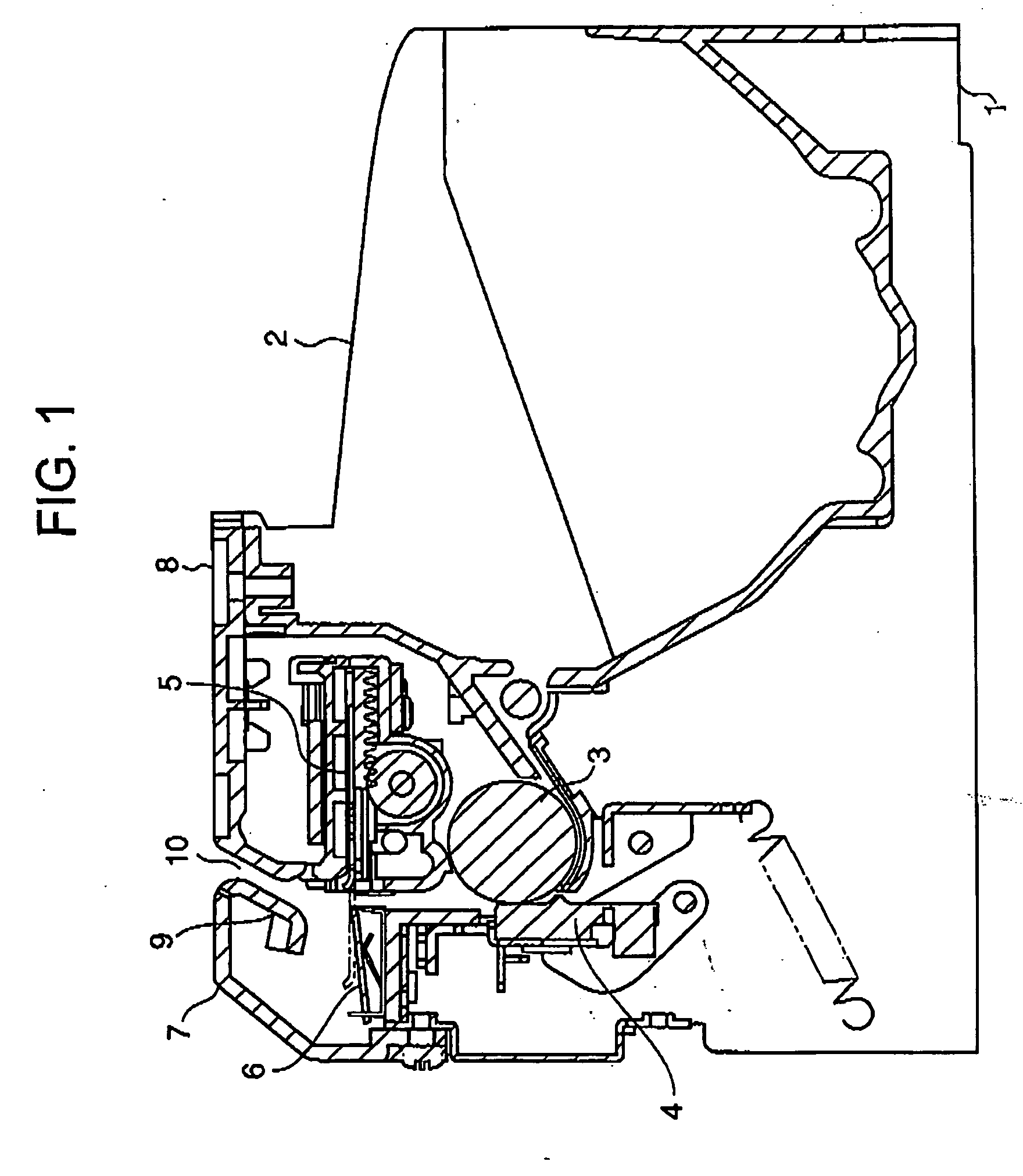
[0031]FIG. 1 partially shows a cross-section of a printer according to an embodiment of the present invention. The illustrated printer has a lower frame 1, an upper frame 2, a platen roller 3 attached to the upper frame 2, and a thermal head 4 attached to the lower frame 1. The upper frame 2 is configured to be opened and closed with respect to the lower frame 1. A roller (not shown) for continuously supplying a paper for printing is mounted on the lower frame 1. A roll paper is introduced from the roller through a paper passage into a space between the platen roller 3 and the thermal head 4. The thermal head 4 prints on the roll paper.

[0032] Further, the roll paper is supplied in a vertical direction from the space between the platen roller 3 and the thermal head 4 to a cutter unit. The illustrated cutter unit has a movable blade unit 5 attached to the upper frame 2 and a stationary blade unit 6 attached to the lower frame 1. A paper passage is defined between the platen roller 3 ...


PUM


Abstract

A plurality of ribs are provided on a cut paper discharge guide and an upper cover which define a discharge port for discharging a cut paper. The ribs hold a cut paper in width direction. Even if a cut paper having a high degree of curl is supplied when a roll diameter of a roll paper is reduced, it is possible to prevent a paper jam such as falling or clogging of the cut paper. It is desirable that the ribs provided on the cut paper discharge guide and the upper cover are disposed in an alternate pattern along the width direction of the discharge port. This arrangement is particularly effective in a printer having an inclined paper passage.

Description

[0001] This application claims priority to prior application JP2005-266320, the disclosure of which is incorporated herein by reference. BACKGROUND OF THE INVENTION [0002] 1. Field of the Invention [0003] The present invention relates to a printer having functions of recording on an integrated roll paper, then cutting the roll paper by a cutter, and discharging the cut paper to an exterior of the printer. The present invention also relates to a cut paper discharge mechanism used for such a printer, and to a paper jam prevention method used in such printer. [0004] 2. Description of the Related Art [0005] Generally, this type of printer has a structure in which a thermal head, a cutter unit, and a discharge port are arranged in a vertical direction. With such an arrangement, a paper is discharged through a paper passage extending in a vertical direction from the cutter unit, which is disposed at a lower portion of the printer, toward the discharge port, which is disposed at an upper p...

Claims


Application Information

Patent Timeline
IPC IPC(8): B41J11/00
CPCB41J11/0045B41J11/006B65H2601/10B65H35/06B41J11/70
Inventor YOSHIOKA, YUKIO
Owner NEC PLATFORMS LTD
Why Eureka
Try Eureka