

Electric connector
- Summary
- Abstract
- Description
- Claims
- Application Information
AI Technical Summary
Benefits of technology
Problems solved by technology
Method used
Image

Examples
Embodiment Construction
[0028] Hereinafter, a preferred embodiment of the present invention will be described in detail with reference to the attached drawings.
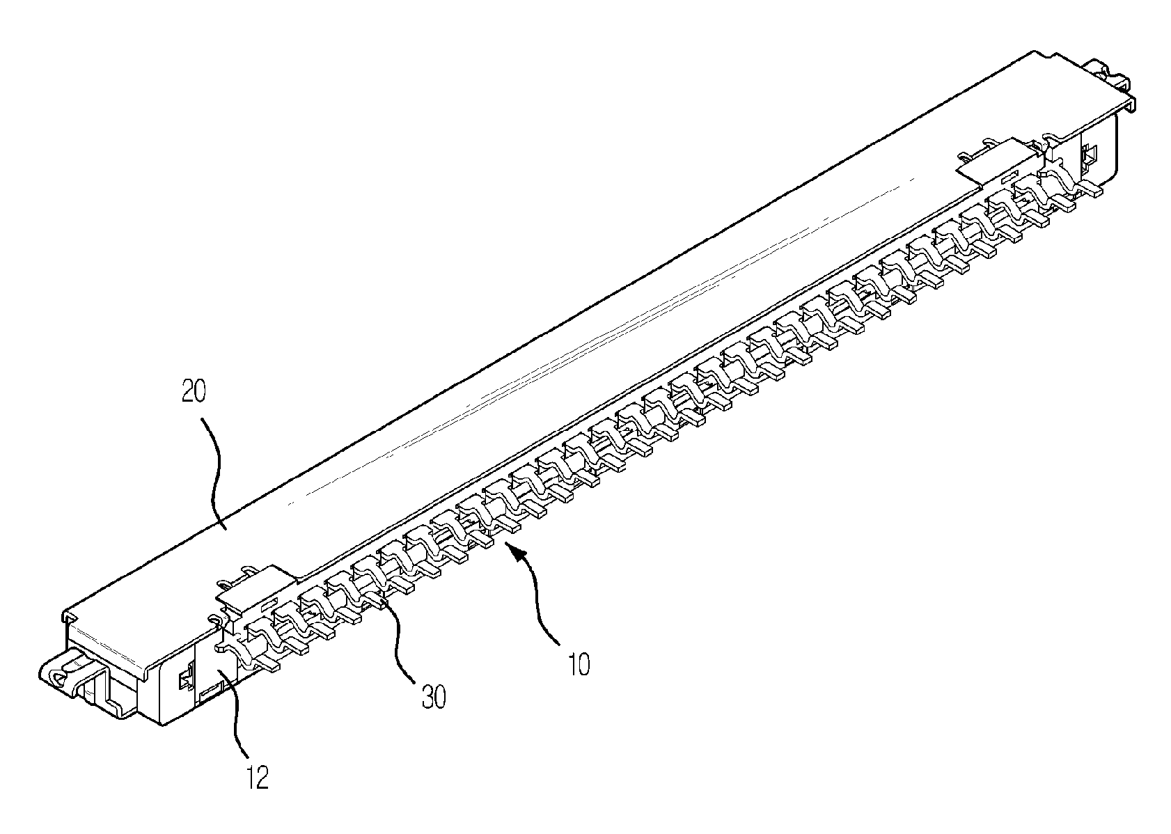
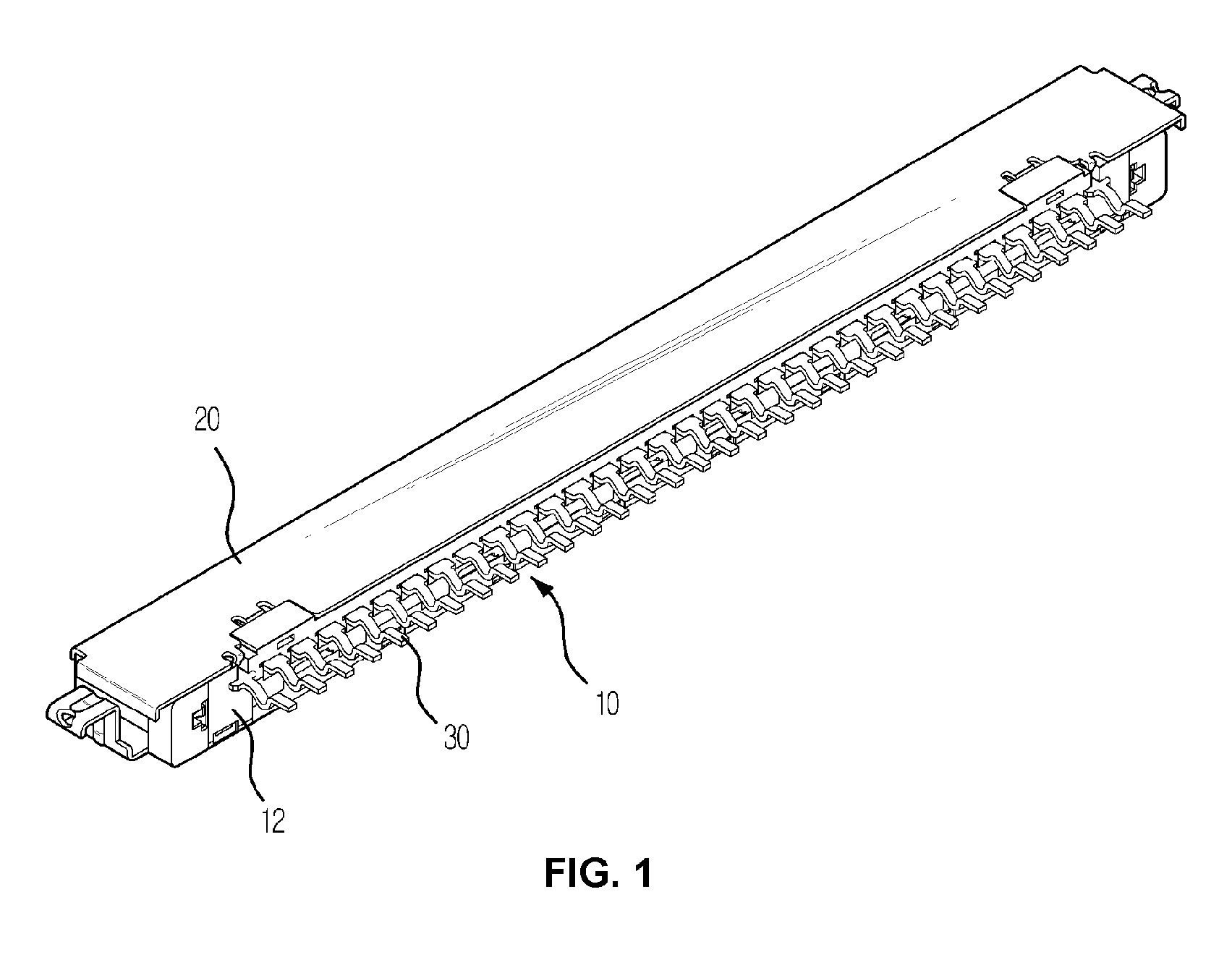
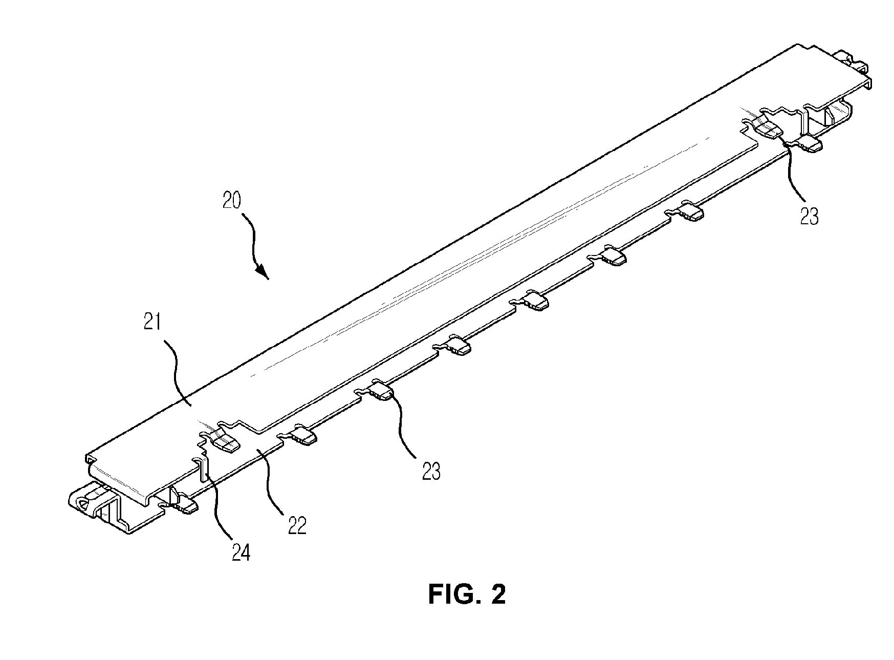
[0029]FIG. 1 is a perspective view showing the external shape of an electric connector, according to the preferred embodiment of the present invention. FIG. 2 is a perspective view of a conductive cover of the electric connector of FIG. 1. Referring to FIGS. 1 and 2, the electric connector according to the preferred embodiment of the present invention includes a main body 10, to which a plurality of main terminal contacts 30 is mounted, and a conductive cover 20 which surrounds the main body 10. A mounting lead of each main terminal contact 30 protrudes outwards from a second surface 12 of the main body 10. The electric connector is constructed such that a separate plug connector (not shown) is inserted into the electric connector through a surface of the main body 10 opposite to the second surface 12. The main body 10 is made of synthetic resin an...
PUM
 Abstract
Description
Claims
Application Information