Golf club head

Inactive Publication Date: 2007-03-22
BRIDGESTONE SPORTS
View PDF18 Cites 30 Cited by
  • Summary
  • Abstract
  • Description
  • Claims
  • Application Information

AI Technical Summary

Benefits of technology

[0022] While the method of bonding the face member to the head body is not particularly restricted according to the present invention, plasma welding, laser welding or electron beam welding is suitable for cleanly finishing bonding portions and for enhancing accuracy of the weight of the club head. Conventional plasma welding may be used for this purpose. A plasma arc generates high temperature energy sufficient to melt materials to be welded together, and the welded materials become solidified after the welding. Conventional laser welding using gas lasers such as CO laser and CO2 laser, and solid state lasers such as YAG laser may also be used. Conventional electron beam welding with appropriate output energy may also be used according to the present invention.
[0023] When the head body is bonded to the face member by plasma, laser or electron beam welding, the gap between the head body and face member may be filled with extra metallic material that is additional to the head body and face member. If such extra material is used, the metallic members do not have to be precisely machined so that no gaps are formed between the head body and face member. Consequently, the cost required for high precision machining of the head body and face member ca

Problems solved by technology

However, since the conventional face member is supported by the head body at the periphery of the face portion, a large improvement of repulsive performance cannot be expected by increasing the maximum width W of the face member unless the maximum height H, which is usually smaller than the maximum width, is also increased.
While it is pa

Method used


Image

  • Golf club head
  • Golf club head
  • Golf club head

Examples


example 1

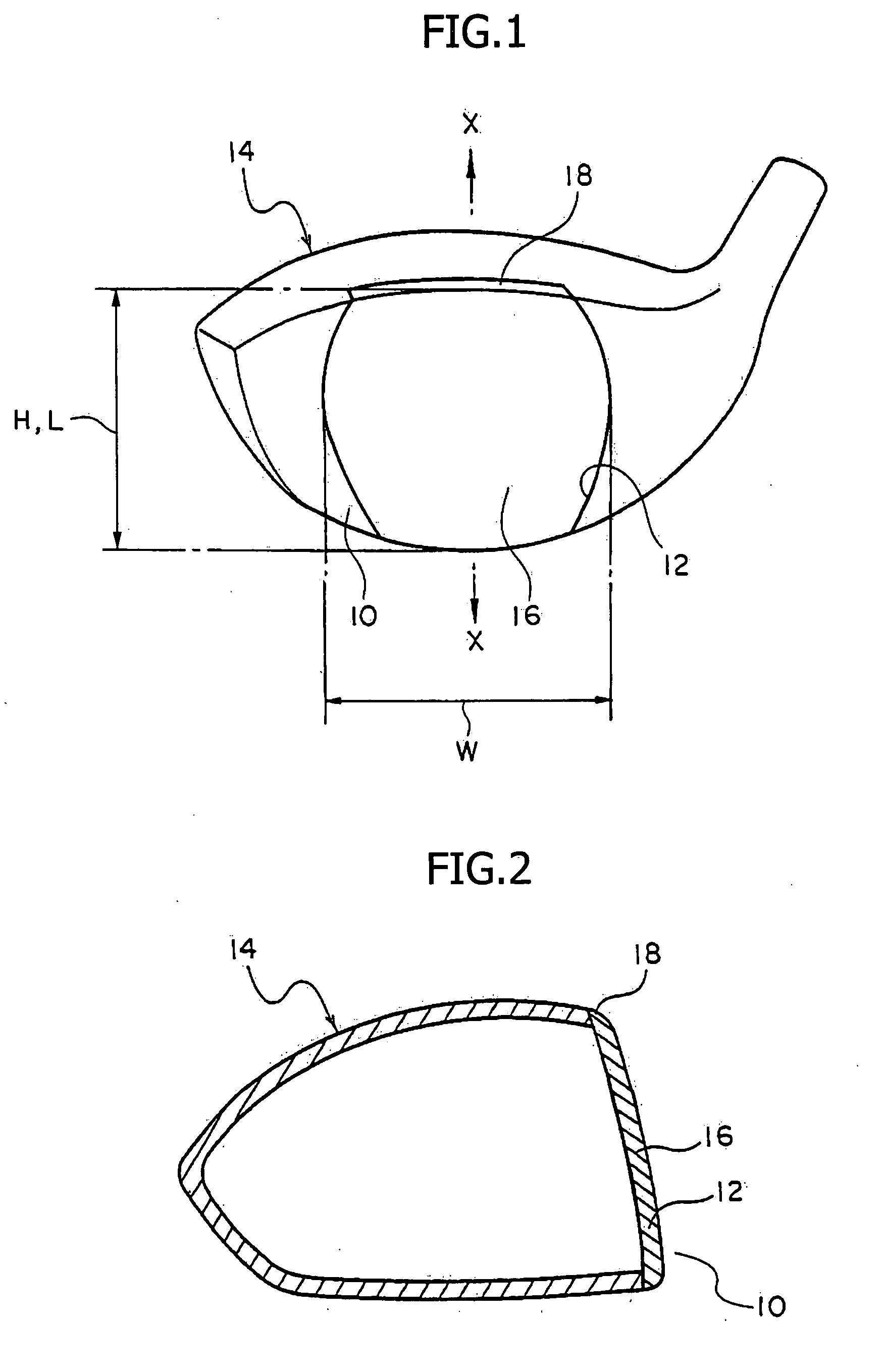
[0056]FIG. 1 is a perspective view showing an example of the club head according to the present invention. FIG. 2 is a cross-sectional view of the club head along the arrow line X-X in FIG. 1, and FIG. 3 is a perspective view of the face member of the club head. The club head of this embodiment is formed into a wood having an internal cavity.

[0057] The club head of this example comprises a head body 14 made of a titanium alloy (specifically, 6-4 Ti cast material), and a face member 16 made of a titanium alloy (specifically, Ti 735 rolled material) for closing a face opening 12 of the head body 14.

[0058] The top edge 12 of the face opening and the top edge of the face member 16 reach the crown portion of the club head. Accordingly, the top edge 18 of the face member 16 serves as a part of the crown portion of the club head when the face member 16 is bonded to the periphery of the face opening 12 of the head body 14.

[0059] According to this example, the face member 16 has a maximum...

example 2

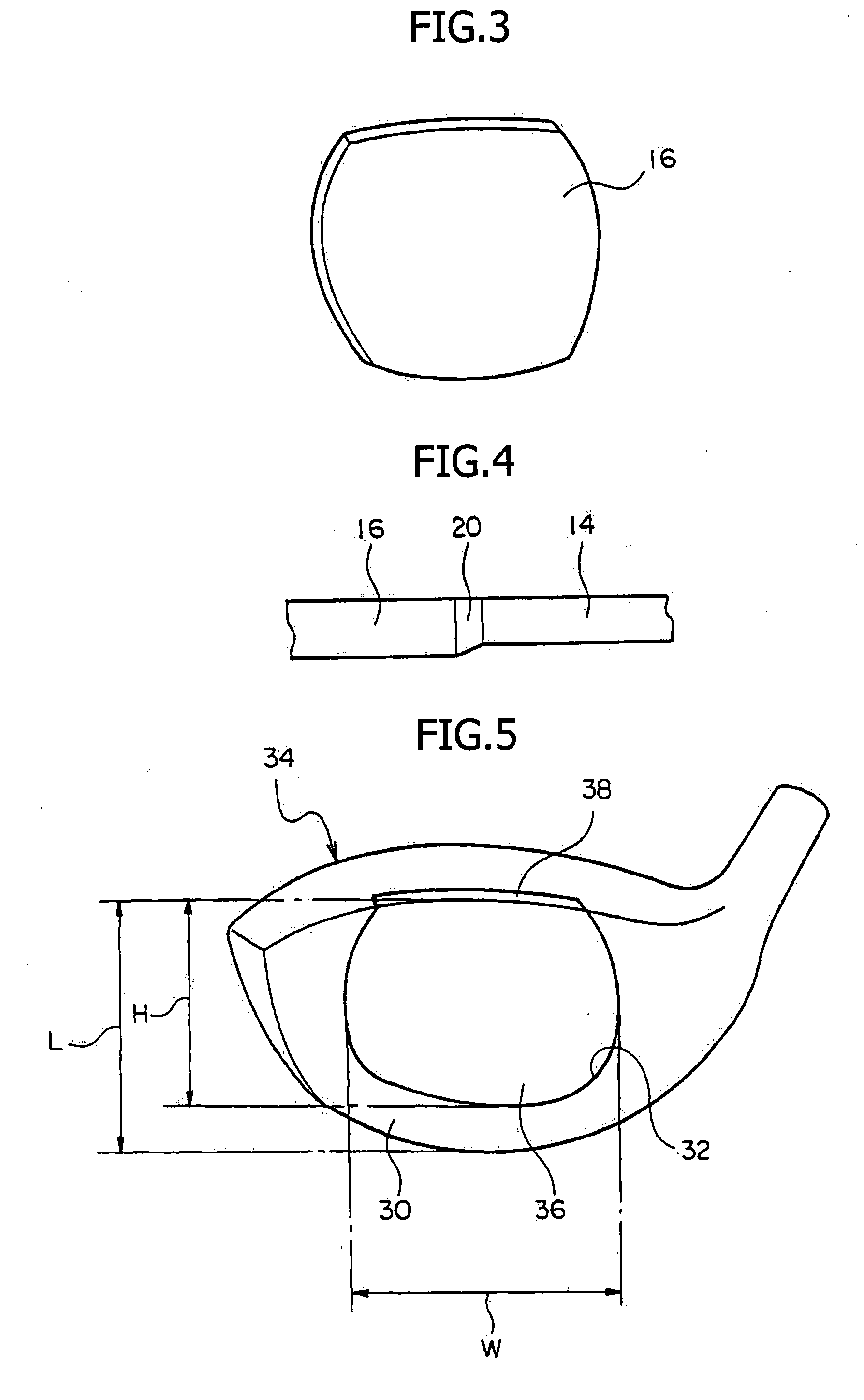
[0061]FIG. 5 is a perspective view showing another example of the club head according to the invention. The club head of this example is formed into a wood club head having a cavity.

[0062] The club head of this example comprises the head body 34 made of titanium alloy (specifically, a cast material of 6-4 Ti) having the face opening 32 on the face portion 30, and the face member 36 made of titanium alloy (specifically, a rolled material of SP700) for closing the face opening 32.

[0063] The top edge of the face opening 32 and the top edge of the face member 36 reach the crown portion of the club head as in example 1. Accordingly, the upper edge 18 of the face member 36 serves as a part of the crown portion when the face member 36 is bonded to the periphery of the face opening 32.

[0064] The maximum height H of the face member 36 is 54 mm, and the maximum width W of the face member 36 is 75 mm. The W / H ratio is 1.389. The maximum height L of the face portion is 59 mm, and the head vo...

example 3

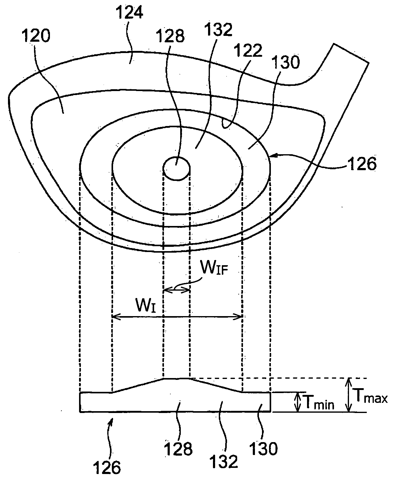
[0070] An example is given for the club head that has differing thicknesses of the face member. On the back side of such a face member an inclined portion is provided as shown in FIG. 9. FIG. 9 shows a club head having a face member that has an inclined portion on the back surface. FIG. 9(a) shows a front view and FIG. 9(b) shows a corresponding cross-sectional view of the face member. The club head comprises a head body 124 having a face opening 122 in the face portion 120, and a face member 126 for closing the face opening 122. A region 128 having the maximum thickness and another region 130 having the maximum thickness are formed on the back surface of the face member 126, and the inclined portion 132 where the thickness continuously changes is provided between the two regions 128 and 130. The region 128 having the maximum thickness contains the centroid of the face portion 120. These regions 128 and 130 may have a circular shape or an ellipsoidal shape which is elongated in the ...


PUM


Abstract

A hollow club head having a head body 14 and a face member 16 bonded to the face opening 12 of the head body 14 is provided, wherein the W/H ratio between the maximum height H (mm) and maximum width W (mm) of the face member is in the range of 1.0 to 1.7, so as to improve cost efficiency associated with improved repulsive speeds of balls hit by the club.

Description

BACKGROUND OF THE INVENTION [0001] 1. Field of the Invention [0002] The invention relates to a hollow golf club head comprising a head body and a face member bonded to a face opening of the head body. [0003] 2. Description of Related Art [0004] Conventional hollow golf club heads comprise a head body and a face member bonded to the face opening of the head body. Examples of face members for such hollow golf club heads include those entirely covering the face portion and those having a shape that approximates the shape of the face surface and that fits within the face surface (for example, see JP 2001-259091 A). SUMMARY OF THE INVENTION [0005] However, since the conventional face member is supported by the head body at the periphery of the face portion, a large improvement of repulsive performance cannot be expected by increasing the maximum width W of the face member unless the maximum height H, which is usually smaller than the maximum width, is also increased. [0006] Titanium and ...

Claims


Application Information

Patent Timeline
IPC IPC(8): A63B53/00A63B53/04A63B102/32
CPCA63B53/0466A63B2053/0416A63B2053/0408A63B2209/00A63B53/047A63B2053/0458A63B53/0458A63B53/0408A63B53/0416
Inventor IMAMOTO, YASUNORIMATSUNAGA, HIDEO
Owner BRIDGESTONE SPORTS
Why Eureka
Try Eureka