IIIuminable retractor

a retractor and retractor technology, applied in the field of retractors, can solve problems such as the negation of the effectiveness of overhead lighting, and achieve the effect of low profile for the curve region

Inactive Publication Date: 2007-03-22
HOWMEDICA OSTEONICS CORP
View PDF13 Cites 64 Cited by
  • Summary
  • Abstract
  • Description
  • Claims
  • Application Information

AI Technical Summary

Benefits of technology

[0023] Preferably the curved region has a major transverse axis of the structural

Problems solved by technology

Unfortunately with such a retractor and its size relativity to the inci

Method used


Image

  • IIIuminable retractor
  • IIIuminable retractor
  • IIIuminable retractor

Examples


Embodiment Construction

Component List: (When Input Light is from a Light Cable):

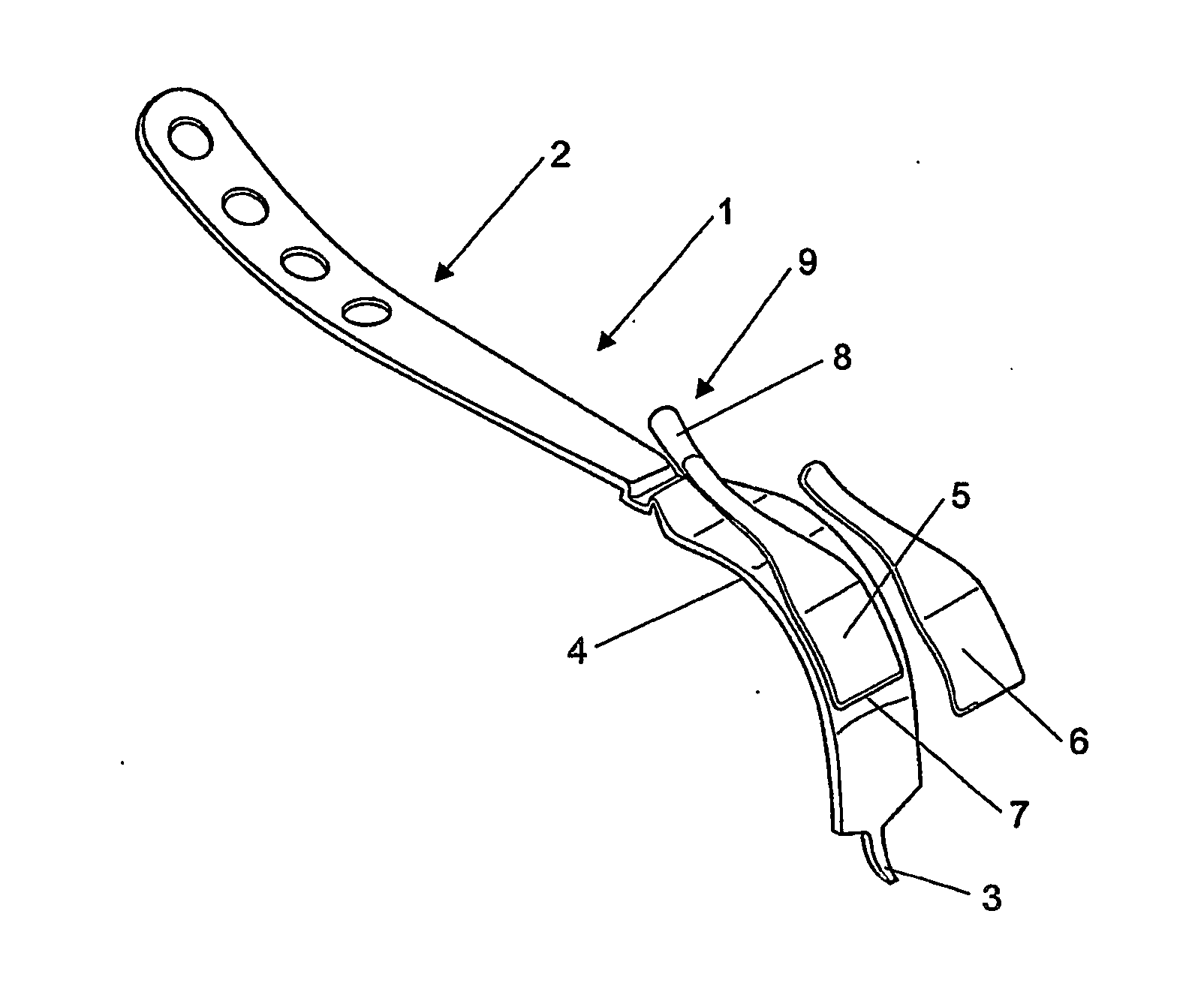
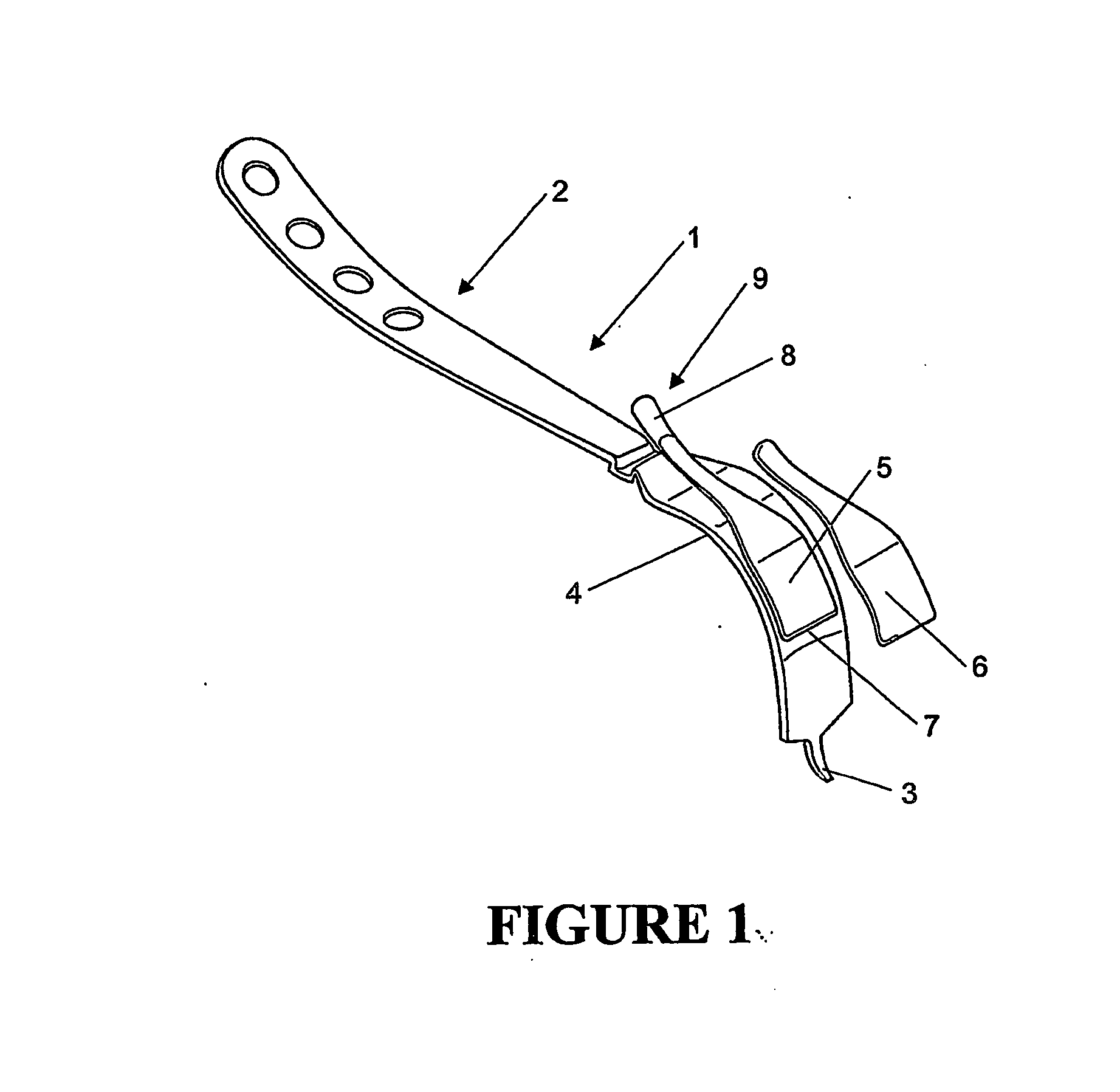
[0137] Retractor; [0138] This could be any retractor, size or shape not critical. Our design as detailed in the drawings is for mini incision and minimally invasive hip replacement. [0139] Manufactured from any suitable material i.e. plastic, carbon fibre, stainless steel, titanium.

[0140] Light Duct; [0141] Clip, this is the attachment point for the light cable and pipe to retractor.

[0142] Attachment to the cable is in the form of a screw connection or push lock type. Material could be plastic (e.g.; ABS, Acetyl, polycarbonate, etc.) or metallic. In some situations this feature could be permanently attached to the retractors. Where the shield is utilised to retain the light duct the role of the clip could be reduced to that of attachment interface between the light duct and light cable or may not be required when the cable detail is moulded directly to the pipe. The clip will in some variants provide some or all of the att...


PUM


Abstract

A retractor assembly suitable for hip or other joint surgery comprising a structural member (1), which consists of a handle (2) that extends proximal through a curved region (4) to a distal region (3) adapted for use in a suitable patient, a light ducting member (5), which is at least in part in substantial conformity to the curved region (4), adapted in use to receive light and reliant on internal reflection of the light, to transmit such received light about at least part of the curved region to an emission outlet (7) which casts light to a zone at and/or about said distal region (3), and a shield (6) overlying at least that part of the light ducting means (5) in substantial conformity to at least part of the curved region (4), wherein the light ducting member (5), the shield (6) and the structural member (1) can be brought into assembly so that directly and/or indirectly each of the light ducting member (5) and the shield (6) is in a supported condition relative to the structural member (1).

Description

[0001] This is a nationalization of PCT / IB04 / 050207 filed Mar. 8, 2004 and published in English.TECHNICAL FIELD [0002] The present invention relates to a retractor useful for minimally invasive and minimal incision hip surgery. BACKGROUND ART [0003] With surgery of the kind referred to above (whether for hip replacement or other purposes) there is a need for a retractor. Unfortunately with such a retractor and its size relativity to the incision there is a negation of the effectiveness of any overhead lighting. [0004] Therefore for this purpose we believe a source of light (preferably of very low profile) associated with the retractor will better allow vision of the distal end regions of the retractor. [0005] Various retractors have been proposed. See for example, U.S. Pat. Nos. 5,928,139 and 6,139,493 and PCT Publication WO 02 / 19919. [0006] The present invention however recognises a need for a retractor (suitable for such hip surgery) [whether an anterior retractor or otherwise] pr...

Claims


Application Information

Patent Timeline
IPC IPC(8): A61B1/32A61B17/02A61B19/00
CPCA61B2019/5206A61B17/02A61B2090/306
Inventor MORRISON, PAULHEYNEN, GRAY FELIX
Owner HOWMEDICA OSTEONICS CORP
Why Eureka
Try Eureka