Head and neck restraint system and device

a head and neck restraint and head and neck technology, applied in the direction of eye treatment, vehicular safety arrangements, pedestrian/occupant safety arrangements, etc., can solve the problem of device restrictions, achieve the effect of improving peripheral vision, reducing the degree of lateral rotation, and reducing the number of devices

Inactive Publication Date: 2007-03-29
SARGENT LEIGH R
View PDF23 Cites 17 Cited by
  • Summary
  • Abstract
  • Description
  • Claims
  • Application Information

AI Technical Summary

Benefits of technology

[0036] Another feature of the present invention is a single, dual attachment tether. The present invention may comprise a single tether attached at each of its ends to the helmet and looped around a rear vertical section of the device. This provides the benefits of allowing the occupant a higher degree of lateral rotation of the head for improved peripheral vision, allows for shorter tethers that will assist in take up during forward impact, and reduce the slippage which takes place in prior art forms of tether attachments. The present invention will be more apparent upon reading the following detailed description in conjunction with the accompanying drawings.

Problems solved by technology

Under general forward impact conditions, the occupant's head motion is controlled with respect to the torso, yet the device will restrictively move with the driver's head and torso along shoulder straps of a seat harness of the vehicle.

Method used


Image

  • Head and neck restraint system and device
  • Head and neck restraint system and device
  • Head and neck restraint system and device

Examples


Embodiment Construction

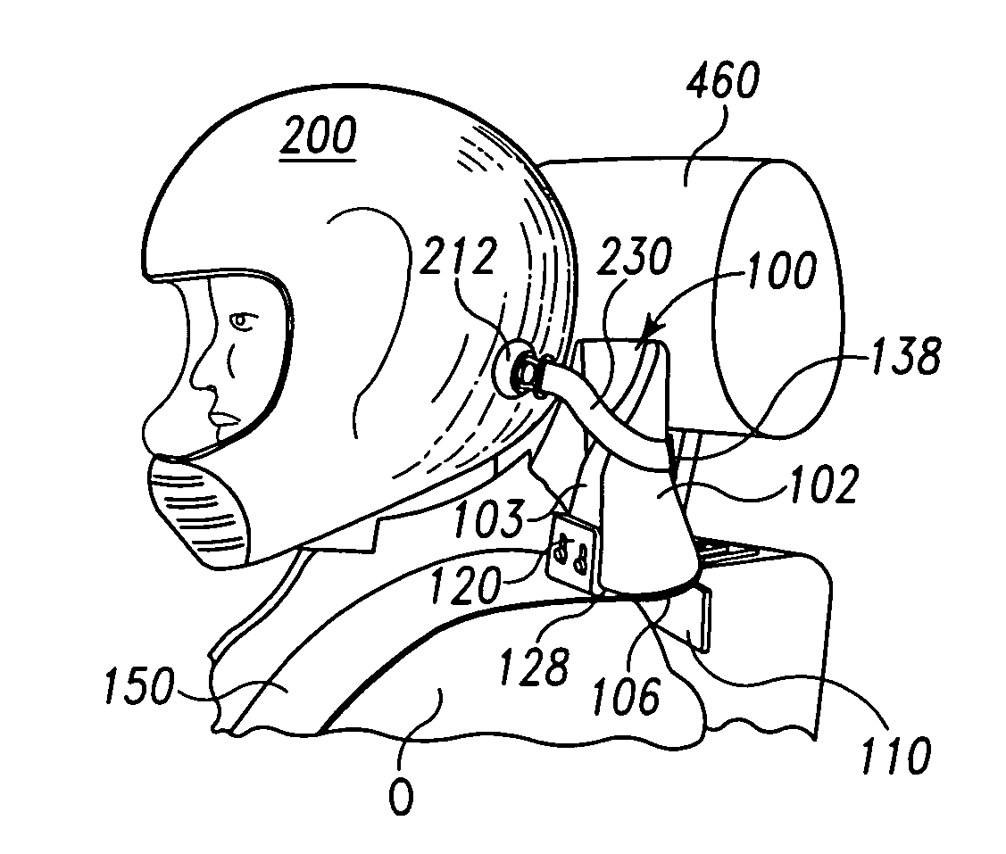
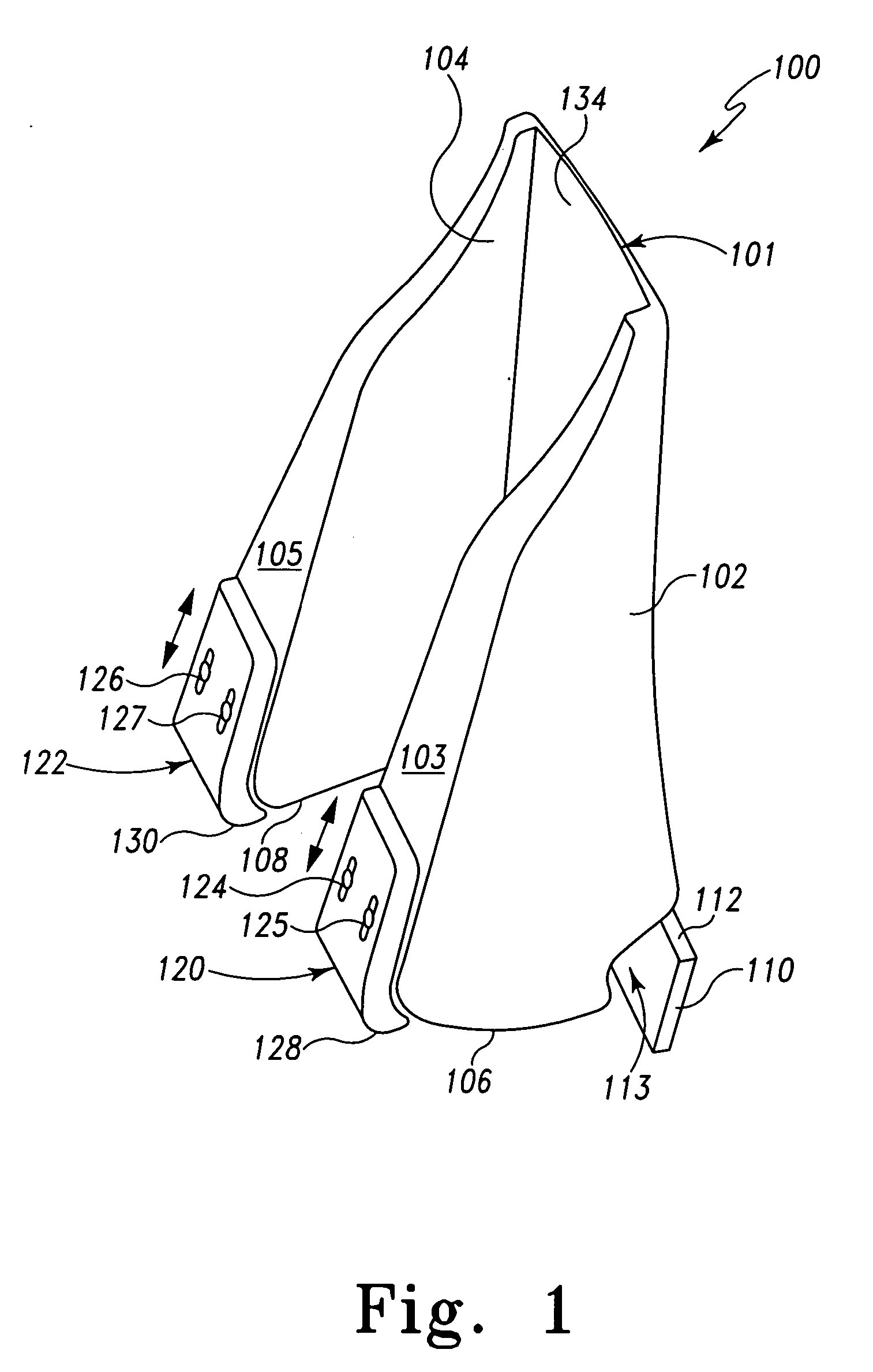
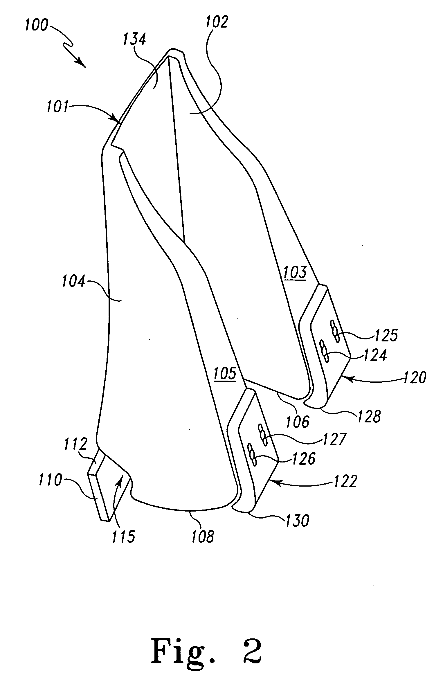
[0055] In FIGS. 1-4, there is depicted various views of an exemplary embodiment of a head and neck restraint device, generally designated 100, that is used to control forces exerted upon an occupant seated in a moving vehicle especially during deceleration of the vehicle. More especially the head and neck restraint device 100 is designed to control forces exerted upon the seated occupant during rapid deceleration of the vehicle such as during an impact. The present head and neck restraint device 100 is useable with cars, aircraft and boats (collectively, vehicles), but especially with all types of high performance vehicles such as race cars. The head and neck restraint device 100 may also be used in conjunction with seated and non-seated static or moving rides such as may be used in amusement parks or other places. As apparent, the head and neck restraint device 100 may be used in various other types of devices.

[0056] An example of use of the head and neck restraint device 100 in a...


PUM


Abstract

A head and neck restraint device controls the motion of the head and forces exerted upon the neck of a seated occupant in a decelerating vehicle. A body defines a collar, right and left legs and right and left wings. The collar is tethered to the helmet. Each leg has belt interaction surfaces that provide a friction action on the shoulder straps. Left and right extensions or wings residing under the shoulder strap rearward of the legs provide a restriction of rotation of the body and thus a binding action on the shoulder straps. A cantilever action is induced in generally forward impact by the tethers pulling on the collar of the body and the binding action on the shoulder straps reducing the forward motion of the body. The present restraint device does not attach to the structure of the vehicle, allows travel thereof with respect to the seated occupant, yet controls the motion of the occupant's head in order to substantially reduce neck loads on the occupant. Moreover present restraint device is not in contact with the occupant during normal operation and thus does not induce discomfort or fatigue. Under general forward impact conditions, the occupant's head motion is controlled with respect to the torso, yet the device will restrictively move with the driver's head and torso along shoulder straps of a seat harness of the vehicle.

Description

CROSS-REFERENCE TO RELATED APPLICATIONS [0001] This patent application claims the benefit of and / or priority to U.S. provisional patent application Ser. No. 60 / 720,517 filed Sep. 26, 2005, entitled “Head and Neck Restraint System and Device” the entire contents of which is specifically incorporated herein by reference.BACKGROUND OF THE INVENTION [0002] 1. Field of the Invention [0003] The present invention relates to head and neck protection devices for use by occupants of a car, aircraft, boat and / or other vehicle to aid in reducing bodily strain, fatigue and injury especially during deceleration of the vehicle. [0004] 2. Background Information [0005] The driver and / or other occupants of high performance cars, planes, boats and / or other vehicles (collectively, ‘vehicles’) typically wear equipment and / or gear designed to provide protection against physical harm during use of the vehicle but especially for providing protection against physical harm during sudden or rapid deceleration...

Claims


Application Information

Patent Timeline
Patent Type & Authority Applications(United States)
IPC IPC(8): A41D13/00
CPCA42B3/0473B60R22/001B64D10/00B60R2021/0086B60R2021/0048
Inventor SARGENT, LEIGH R.
Owner SARGENT LEIGH R
Why Eureka
Try Eureka