
Chipper feed mechanism with pulsating down pressure

a feed mechanism and pulsating technology, applied in the direction of cocoa, grading, solid separation, etc., can solve the problem of only responding to the increase in hydraulic fluid pressure, and achieve the effect of facilitating the movement of feed materials

Active Publication Date: 2007-03-29
ALAMO GROUP
View PDF3 Cites 17 Cited by
  • Summary
  • Abstract
  • Description
  • Claims
  • Application Information

AI Technical Summary

Benefits of technology

[0005] The present invention provides a method comprising the steps of rotating a feed wheel of a wood chipper to facilitate moving feed material toward a cutting assembly of the wood chipper via a gap defined between the

Problems solved by technology

While this system has its advantages, it is also limited by the fact that the increased load on the feed wheel motor and thus the increased pressure on the hydraulic fluid can only be responded to by the increased down pressure of the feed drum.

Method used


Image

  • Chipper feed mechanism with pulsating down pressure
  • Chipper feed mechanism with pulsating down pressure
  • Chipper feed mechanism with pulsating down pressure

Examples


Embodiment Construction

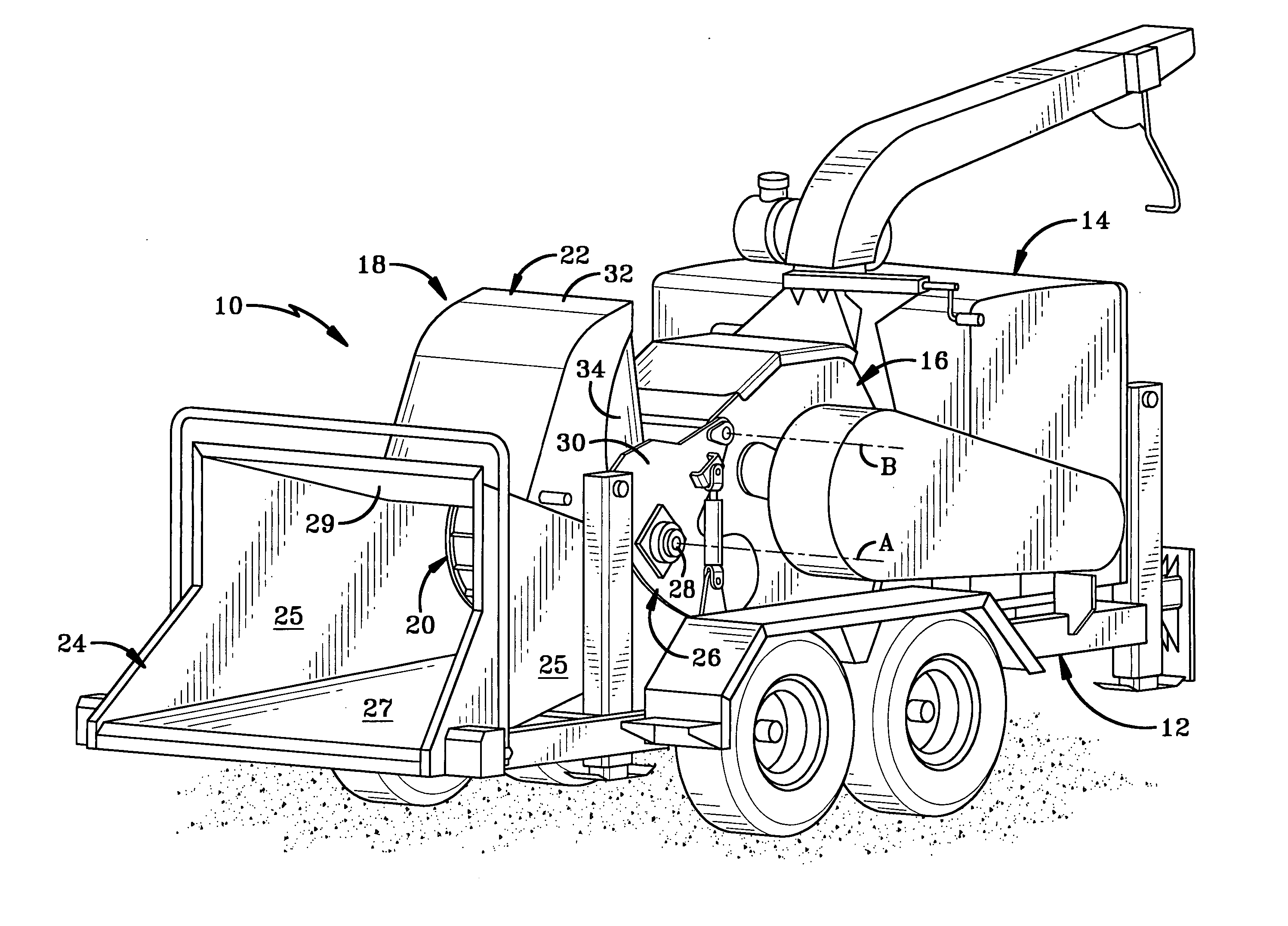
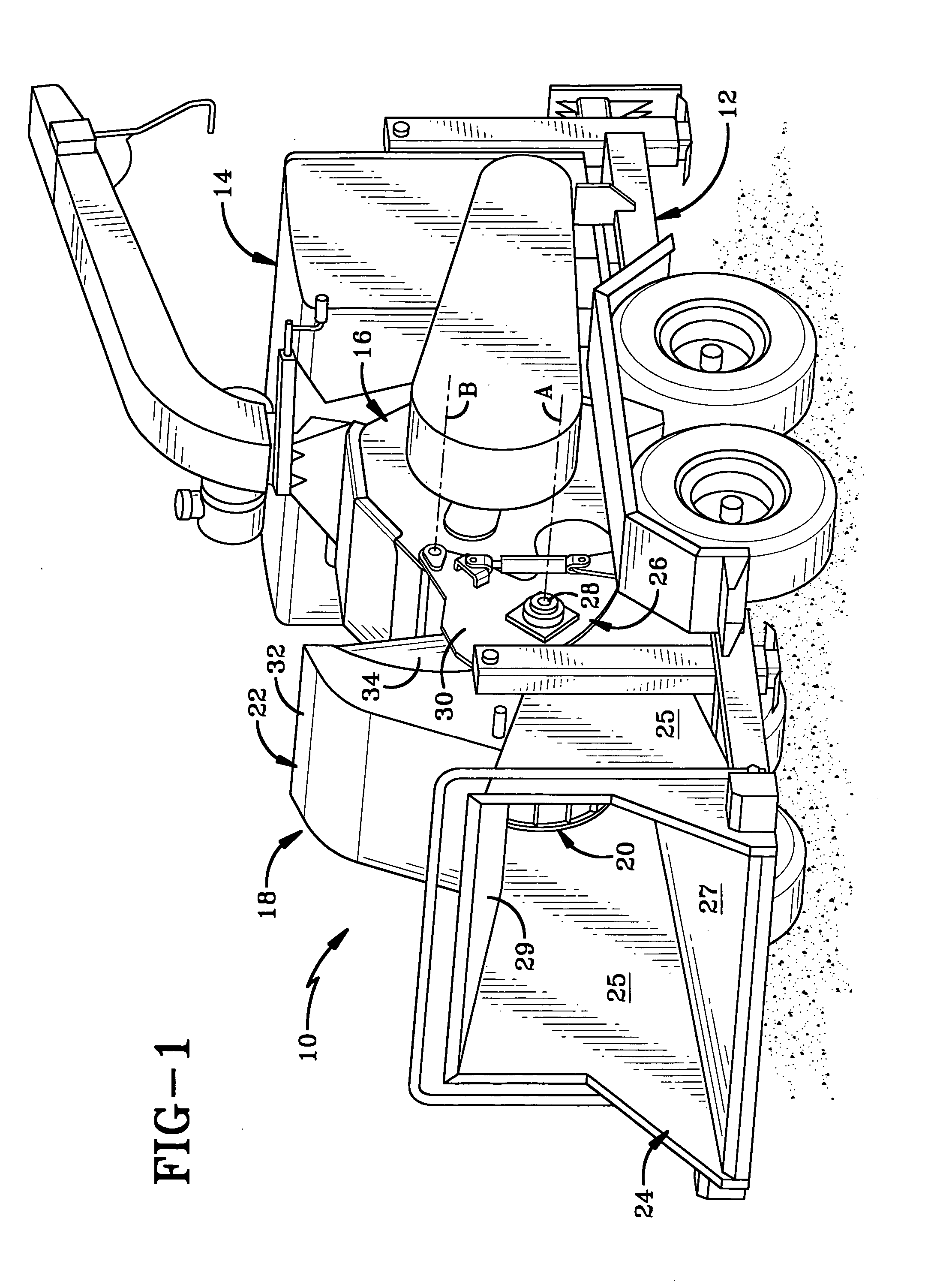
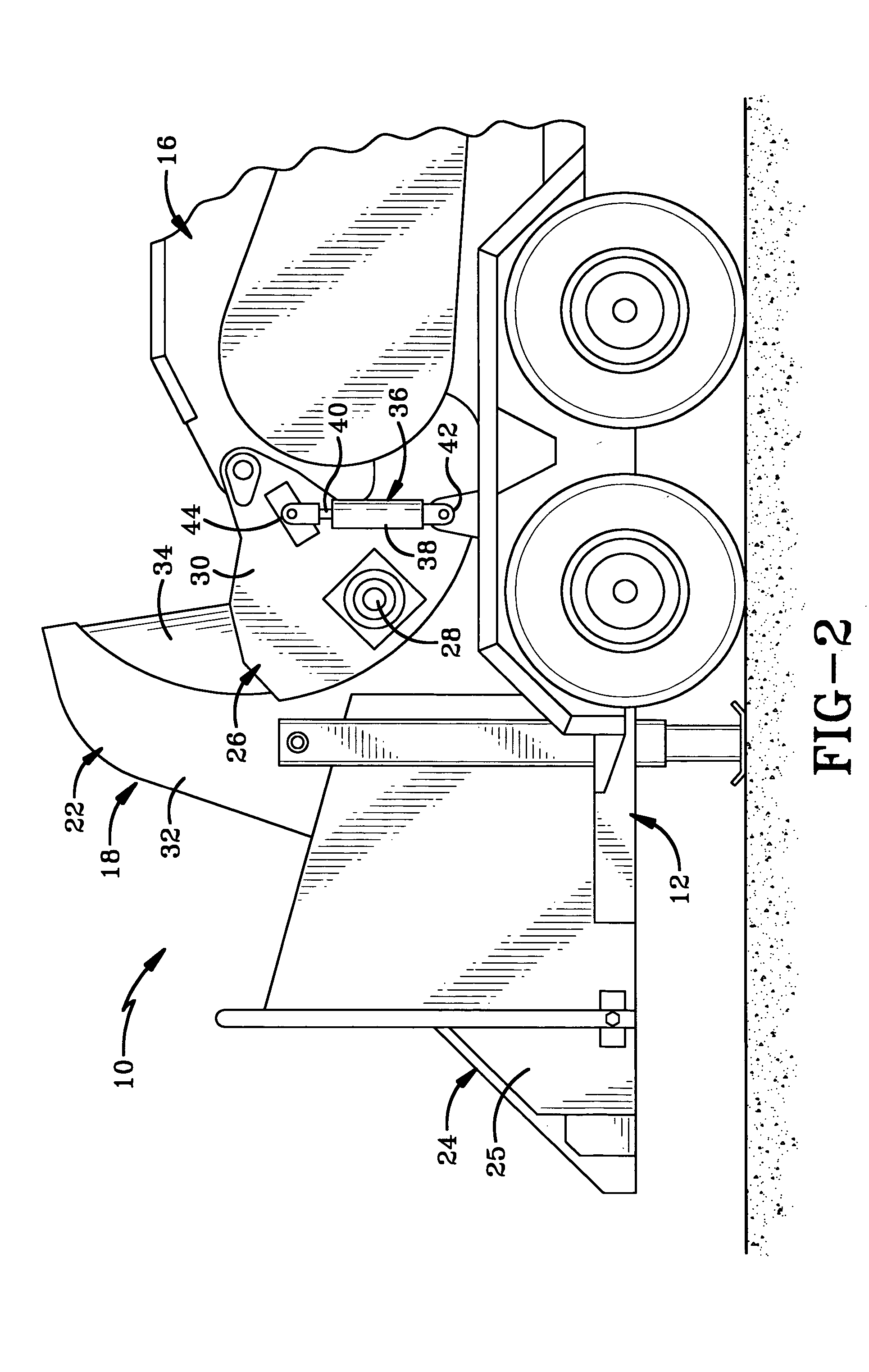
[0013] The wood chipper of the present invention is indicated generally at 10 in FIG. 1. Wood chipper 10 is configured to control the down pressure typically applied by the feed wheel thereof in virtually any manner desired. In one preferred embodiment, wood chipper 10 is configured to apply increased force or pressure in a pulsating manner to feed material being fed into the wood chipper in order to improve the feeding characteristics thereof.

[0014] Wood chipper 10 is a wheeled vehicle having a frame 12 with an engine 14 mounted thereon. A cutting assembly 16 is mounted on frame 12 and is operatively connected to and powered by engine 14. A feed wheel assembly 18 is mounted on frame 12 adjacent cutting assembly 16 and opposite engine 14. Feed wheel assembly 18 includes a feed wheel 20 rotatably mounted within a feed wheel housing 22. A feed chute 24 is mounted adjacent feed wheel housing 22 whereby feed material may be fed through feed chute 24 into housing 22 and be drawn by feed...


PUM


Abstract

A wood chipper includes an engine and a cutting assembly. A rotatable feed wheel and a gap-bounding member define therebetween an adjustable gap through which feed material moves toward the cutting assembly. An electronic control unit (ECU) controls force applied to the feed wheel or gap-bounding member toward the feed material in response to an operational condition of the wood chipper. The ECU can maintain or vary the force in any desired manner. One option is to apply the force with a pulsating mechanism in a pulsating manner to enhance the feeding procedure. The pulsating mechanism is in communication with a sensor from which the ECU receives signals typically indicating an operational speed of the cutting assembly or the engine. An ECU logic circuit permits the pulsating force only if the operational speed exceeds a predetermined threshold.

Description

BACKGROUND OF THE INVENTION [0001] 1. Technical Field [0002] The invention relates generally to wood chippers. More particularly, the invention relates to a control system for controlling the feed wheel of a wood chipper in order to provide improved feeding characteristics of the wood chipper. Specifically, the invention relates to such a control system in which the feed wheel is able to move up and down while rotating in order to provide increased down pressure on feed material in a pulsating manner. [0003] 2. Background Information [0004] Typically, wood chippers include a feed chute, a rotating feed wheel and a cutting assembly whereby feed material is fed through the feed chute and drawn in by the feed wheel to the cutting assembly where the feed material such as branches and the like are cut by the cutting assembly. Some wood chippers utilize a single feed wheel while others utilize a pair of feed wheels which rotate in opposite directions to draw the feed material into the cut...

Claims


Application Information

Patent Timeline
IPC IPC(8): B02C25/00
CPCB02C18/2283B02C2201/066B02C25/00
Inventor HARTZLER, MARK A.EGLIN, JOHN J.
Owner ALAMO GROUP
Learn More