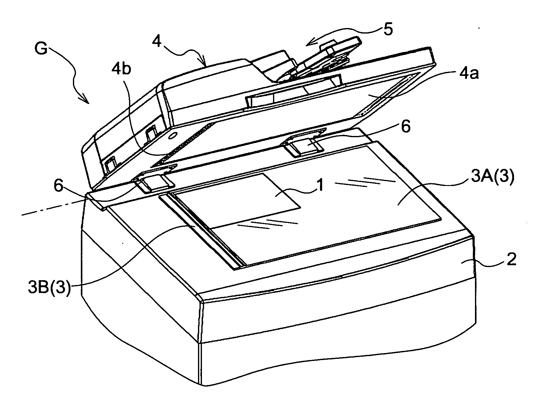
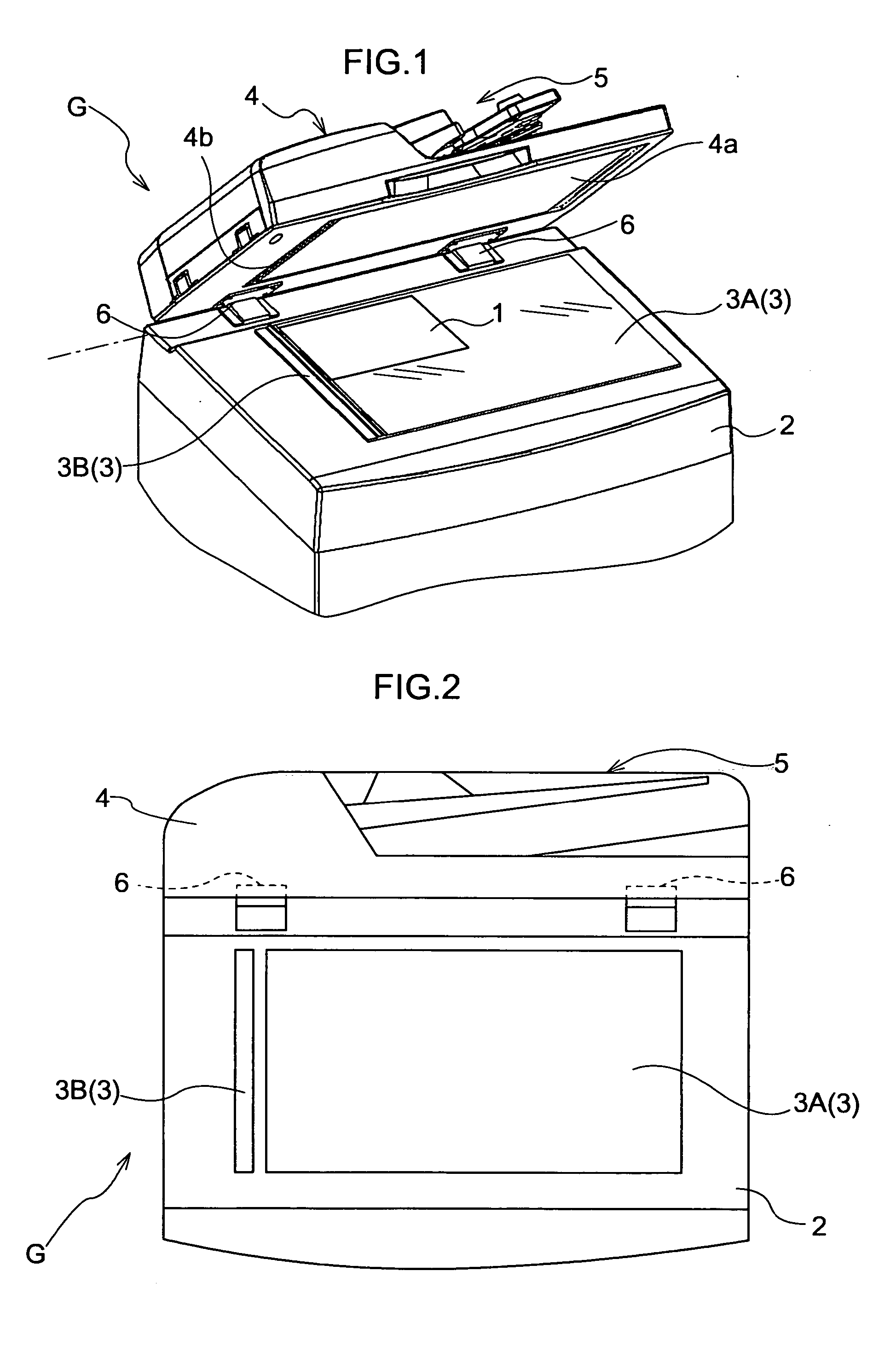
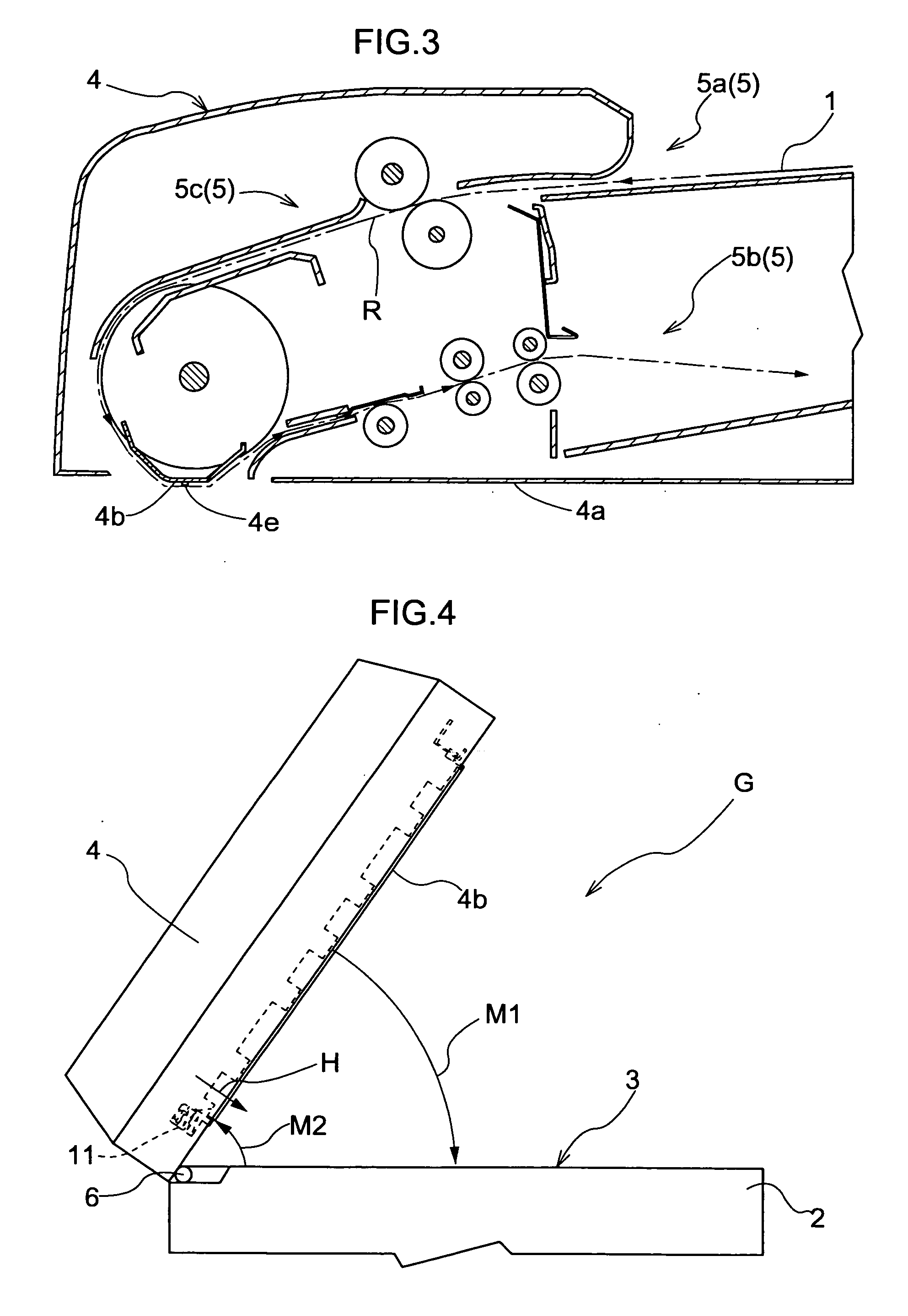
Image forming apparatus
a technology of image forming and forming parts, which is applied in the direction of electrographic process equipment, thin material processing, instruments, etc., can solve the problems of document reading operation, difficulty in realizing such high precision attachment, and a portion of reading guide, etc., and achieves the effect of easy assembly of the apparatus
- Summary
- Abstract
- Description
- Claims
- Application Information
AI Technical Summary
Benefits of technology
Problems solved by technology
Method used
Image
Examples
first embodiment
[0080]FIG. 5 is a perspective view of principal portion showing a mode of attachment of the reading guide 4b to a frame F of the cover means 4 according to a first embodiment. FIG. 6 is a detailed view of the first end portion 4ba of the reading guide 4b and FIG. 7 is a detailed view of the second end port ion 4bb of the reading guide 4b.
[0081] In this first embodiment, the first end portion 4ba (including its vicinity) of the reading guide 4b is attached to be movable toward / away from the cover means 4. Further, there is provided an urging means for urging the first end portion 4ba toward the automatic reading area 3B. On the other hand, the second end portion 4bb (including its vicinity) of the reading guide 4b is attached to be immovable relative to the cover means 4.
[0082] As shown in FIG. 6, at the first end portion 4ba of the reading guide 4b, there are provided first engaging claws 9 projecting along the height thereof. At corresponding opposing portions of the frame F, the...
second embodiment
[0090]FIG. 8 is a perspective view of principal portion showing a further mode of attachment of the reading guide 4b to the frame F of the cover means 4 according to a second embodiment.
[0091] In this second embodiment, both the first end portion 4ba side and the second end portion 4bb side of the reading guide 4b are attached to be movable to / away from the cover means 4. And, a first coil spring (corresponding to “first urging means”) 11a and a second coil spring (corresponding to “second urging means”) 11b are provided for urging the first end portion 4ba side and the second end portion 4bb side toward the automatic reading area 3B, respectively. The specific construction for attaching the first end portion 4ba and the second end portion 4bb of the reading guide 4b to the frame 4 of the cover means 4 is identical to the attaching construction of the first end portion 4ba side in the above-described first embodiment.
[0092] In this second embodiment, the respective urging forces o...
third embodiment
[0095]FIG. 9 is a perspective view of principal portion showing a further mode of attachment of the reading guide 4b to the frame F of the cover means 4 according to a third embodiment.
[0096] In this third embodiment, the first end portion 4ba side is attached to be movable to / away from the cover means 4, whereas the second end portion 4bb side is attached to be immovable relative to the cover means 4, but no urging means is provided in the reading guide 4b. Namely, the reading guide 4b of this third embodiment is identical to a modified construction of the reading guide 4b of the first embodiment shown in FIG. 5, with omission of the coil spring 11 provided on the first end portion 4ba side thereof.
[0097] When the cover means 4 is closed, due to the dead load of the reading guide 4b, the first end portion 4ba side thereof slightly project from the lower face position (the position of the covering portion 4a) of the cover means 4. Under the closed condition of the cover means 4, t...
PUM
 Abstract
Description
Claims
Application Information
 - R&D
- Intellectual Property
- Life Sciences
- Materials
- Tech Scout
- Unparalleled Data Quality
- Higher Quality Content
- 60% Fewer Hallucinations
Browse by: Latest US Patents, China's latest patents, Technical Efficacy Thesaurus, Application Domain, Technology Topic, Popular Technical Reports.
© 2025 PatSnap. All rights reserved.Legal|Privacy policy|Modern Slavery Act Transparency Statement|Sitemap|About US| Contact US: help@patsnap.com


