Magnetic recording media and magnetic recording device
a magnetic recording and recording media technology, applied in the field of magnetic recording media, can solve the problems of servo snr, interference between adjacent tracks, and inability to meet the needs of the user,
- Summary
- Abstract
- Description
- Claims
- Application Information
AI Technical Summary
Problems solved by technology
Method used
Image

Examples
example 1
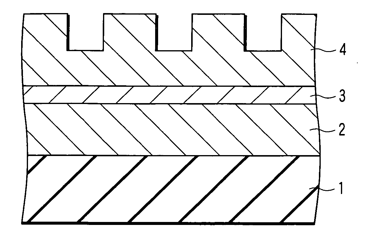
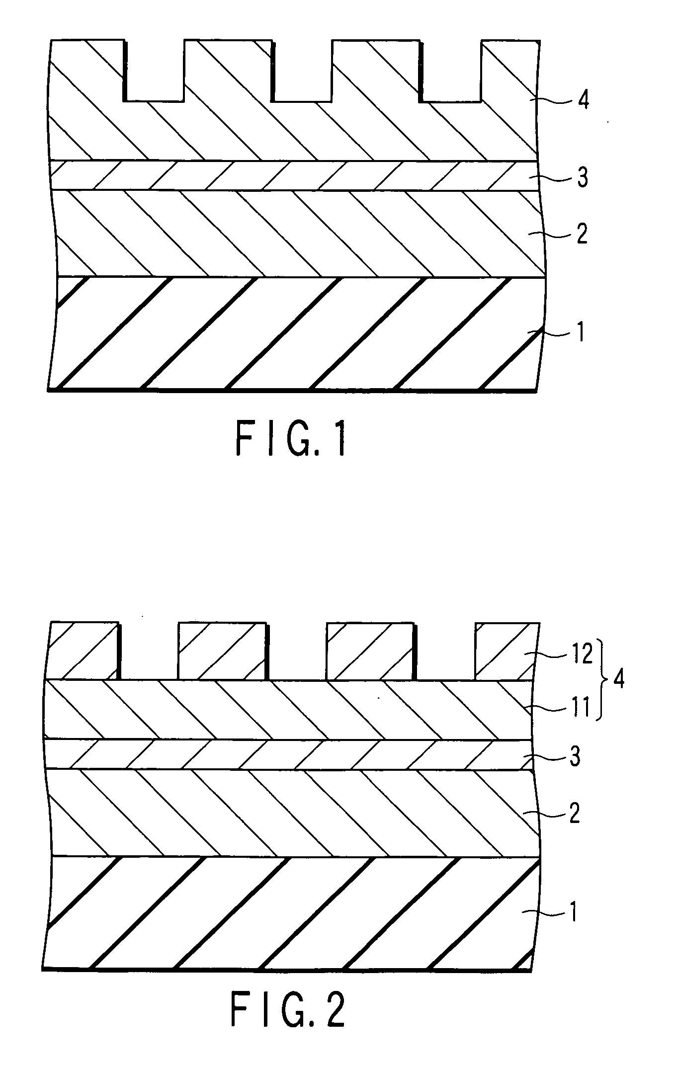
[0058] In the present embodiment, the DTR media whose servo area has the structure shown in FIG. 2 is manufactured. On the substrate 1, the soft underlayer 2 made of CoZrNb having a thickness of 120 nm, the intermediate layer 3 made of Ru having a thickness of 20 nm, and the magnetic recording layer 4 that comprises the lower granular layer 11 made of CoCrPt-SiO2 having a thickness of 10 nm and the topcoat layer 12 made of CoCrPt having a thickness of 10 nm are stacked in this order. Then, a DLC film is formed as a protective layer. After forming the DLC film, the magnetic recording layer 4 is processed by employing the imprint method. In this processing, only the topcoat layer 12 is etched with the etching depth set to 10 nm, thereby obtaining a media having the structure shown in FIG. 2.
[0059] As shown in FIG. 2, the magnetic recording layer 4 is not completely separated in the depth direction, and coercivity of the protrusions is different from that of thin film portions. In the...
example 2
[0065] In the present embodiment, the DTR media whose servo area has the structure shown in FIG. 4 is manufactured. On the substrate 1, the soft underlayer 2 made of CoZrNb having a thickness of 120 nm, the intermediate layer (seed layer) 3 made of NiFeCr having a thickness of 20 nm, and the magnetic recording layer 4 that comprises the lower ferromagnetic layer 21, the nonmagnetic metal layer 22 made of Ru having a thickness of 0.5 nm, and the upper ferromagnetic layer 23, are stacked in this order. The lower ferromagnetic layer 21 is a multilayer film [Co(0.3 nm) / Pd(1.0 nm)]5 having five Co films of 0.3 nm and five Pd films of 1.0 nm which are stacked alternately. The upper ferromagnetic layer 23 is a multilayer film [Co(0.3 nm) / Pd(1.0 nm)]10 having ten Co films of 0.3 nm and ten Pd films of 1.0 nm which are stacked alternately. Then, after forming the magnetic recording layer, a DLC film is formed on the magnetic recording layer as a protective layer. After forming the DLC film, ...
example 3
[0069] In the present embodiment, the DTR media whose servo area has the structure shown in FIG. 5 is manufactured. On the substrate 1, the soft underlayer 2 made of CoZrNb having a thickness of 120 nm, the intermediate layer (seed layer) 3 made of PdSiO having a thickness of 20 nm, and the magnetic recording layer 4 that comprises the ferromagnetic layer 31 being a multilayer film [Co(0.3 nm) / Pd(1.0 nm)]5, the nonmagnetic metal layer 32 made of PdSi, and the soft magnetic layer 33 of the granular structure are stacked in this order. Then, after forming the magnetic recording layer, a DLC film is formed on the magnetic recording layer as a protective layer. After forming the DLC film, the magnetic recording layer 4 is processed by the imprint method. In this processing, only the soft magnetic layer 33 is etched with the etching depth set to 6.5 nm, thereby obtaining a media having the structure shown in FIG. 5.
[0070] In the present embodiment, the ferromagnetic layer 31 and the sof...
PUM
| Property | Measurement | Unit |
|---|---|---|
| thickness | aaaaa | aaaaa |
| grain diameter | aaaaa | aaaaa |
| thickness | aaaaa | aaaaa |
Abstract
Description
Claims
Application Information
 - R&D
- Intellectual Property
- Life Sciences
- Materials
- Tech Scout
- Unparalleled Data Quality
- Higher Quality Content
- 60% Fewer Hallucinations
Browse by: Latest US Patents, China's latest patents, Technical Efficacy Thesaurus, Application Domain, Technology Topic, Popular Technical Reports.
© 2025 PatSnap. All rights reserved.Legal|Privacy policy|Modern Slavery Act Transparency Statement|Sitemap|About US| Contact US: help@patsnap.com