Magnetic recording apparatus and positioning correction method

a technology of positioning correction and recording apparatus, which is applied in the direction of digital signal error detection/correction, recording signal processing, instruments, etc., can solve the problems of recording failure and reproduction failure, data cannot be written and read accurately, and data cannot be written and read

Inactive Publication Date: 2007-03-29
KK TOSHIBA
View PDF14 Cites 2 Cited by
  • Summary
  • Abstract
  • Description
  • Claims
  • Application Information

AI Technical Summary

Problems solved by technology

However, in the perpendicular magnetic recording method, when the recording density is not lower than 100 Gbit/in2, a writing operation to an adjacent track is performed by side fringing generated from a side face of the magnetic head, which results in a problem that a recording failure and a reproduction failure are generated.
Therefore, in the case where the ideal servo pattern previously assumed and the head are shifted from each other, sometimes the data cannot accurately be written and read because a head positioning center by the servo pattern is shifted from the center of the discrete track in which the data is recorded.
However, in the case where a transfer error is generated in transferring the servo pattern to a substrate during a magnetic recording medium production process, the tracking center does not coincide with the center of the di

Method used


Image

  • Magnetic recording apparatus and positioning correction method
  • Magnetic recording apparatus and positioning correction method
  • Magnetic recording apparatus and positioning correction method

Examples


Embodiment Construction

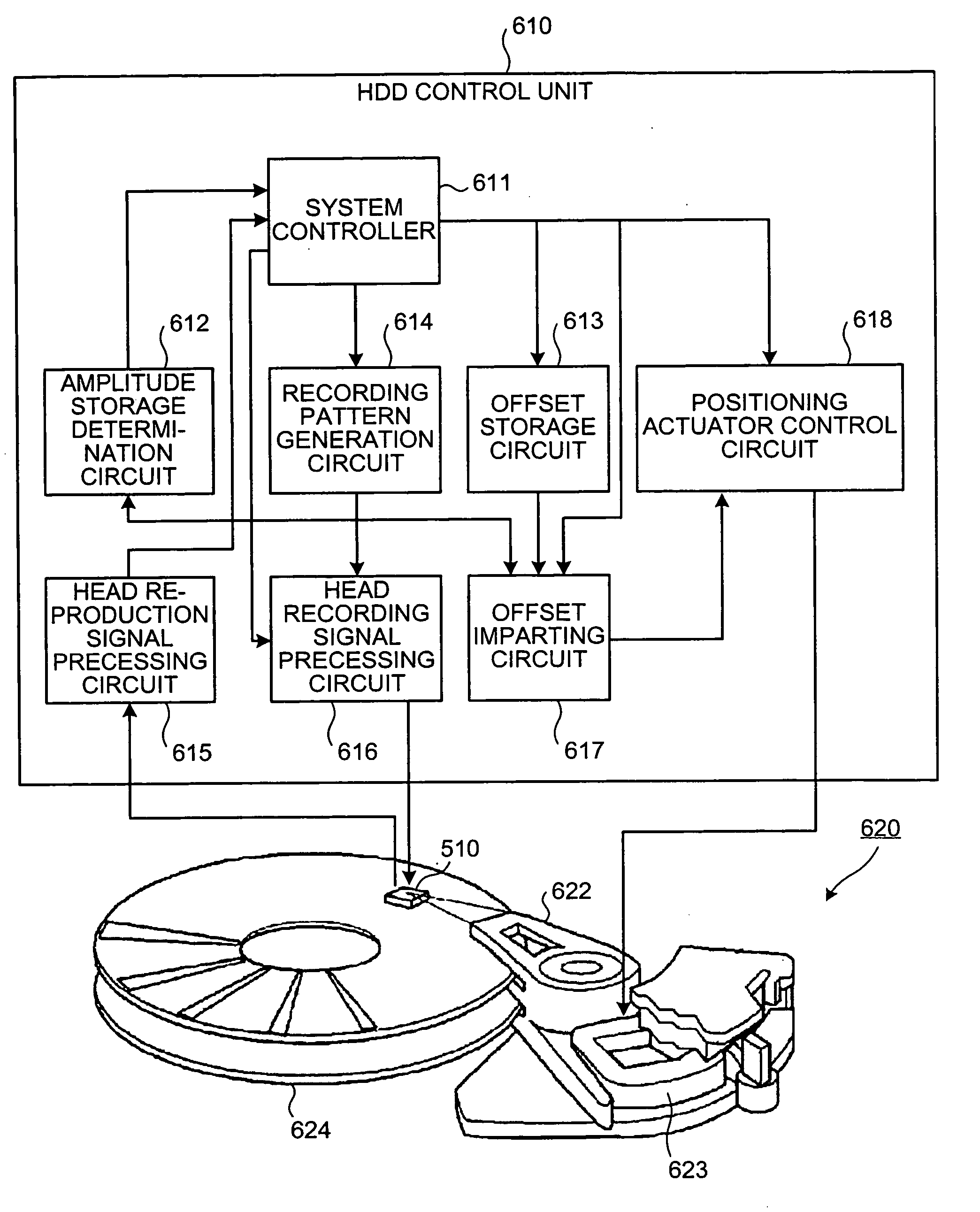
[0036] A magnetic recording apparatus and a positioning correction method of a preferred embodiment according to the invention will be described in detail below with reference to the accompanying drawings. In the embodiment, the magnetic recording apparatus and positioning correction method of the invention are applied to the hard disk drive (HDD) provided with a hard disk (HD) which is of the magnetic recording medium and the positioning correction of a composite magnetic head in HDD respectively.

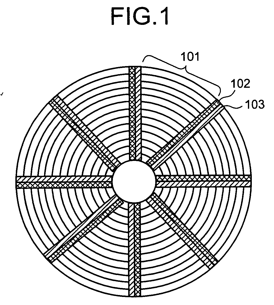
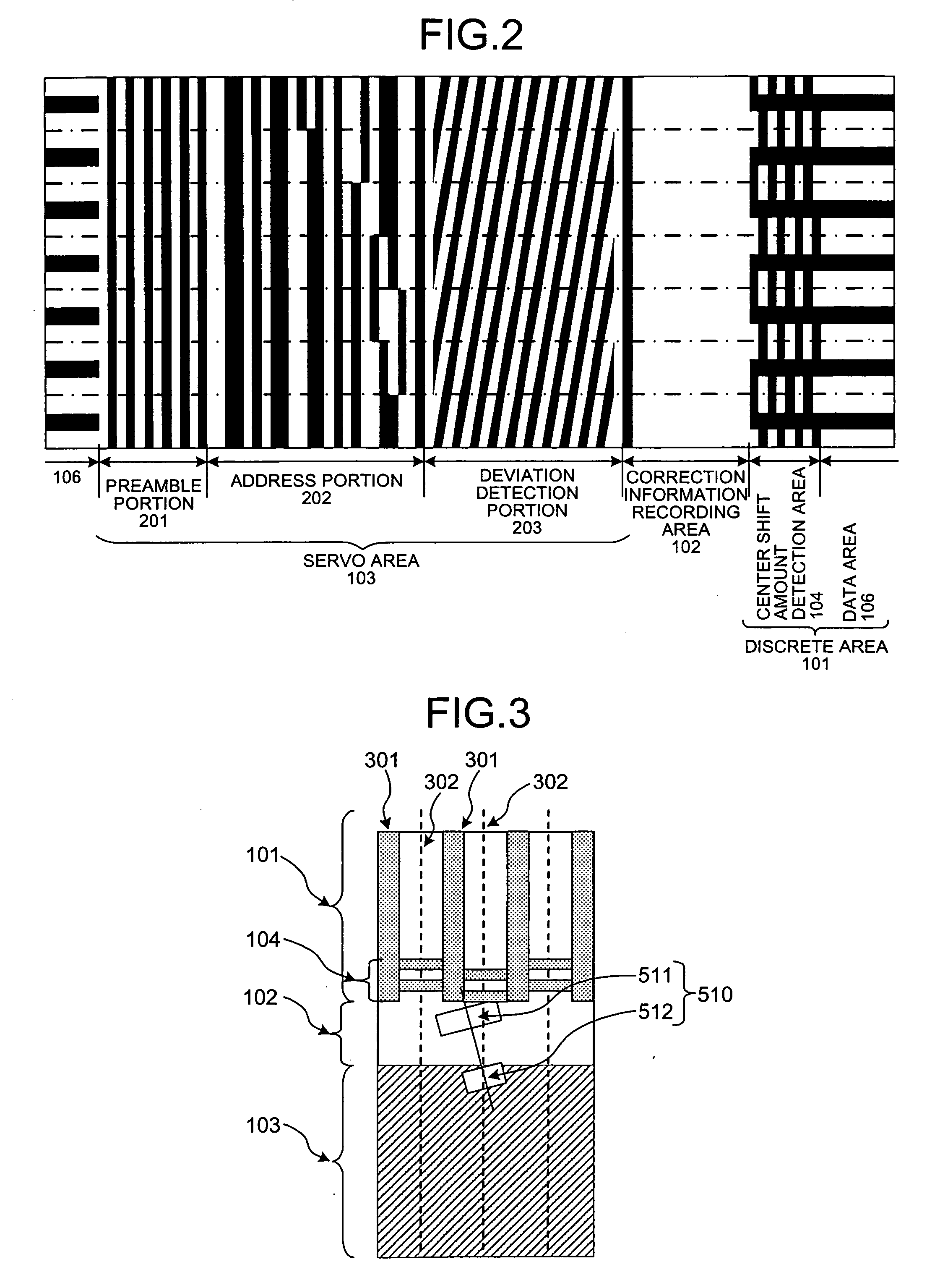
[0037] A structure of the hard disk according to the embodiment will first be described. The hard disk of the embodiment has the structure in which an offset amount measurement area is provided in a radial direction between the discrete area and the servo area. An offset amount is measured in the offset amount measurement area, and the offset amount is a relative distance in a storage-medium radial direction between the reproducing head and the recording head.

[0038]FIG. 1 is a schematic ...


PUM


Abstract

A magnetic recording apparatus includes a composite magnetic head which includes a recording head and a reproducing head; a magnetic storage medium; a discrete area; and a correction information recording area. Positioning correction information is able to be written in the correction information recording area at each track center. The apparatus also includes a center shift amount detection area. Center shift amount detection information is previously recorded in the center shift amount detection area. The center shift amount detection information is for measuring a center shift amount which indicates a relative distance between a tracking center and an actual track center of the discrete area when either the recording head or the reproducing head is positioned at a track center.

Description

CROSS-REFERENCE TO RELATED APPLICATIONS [0001] This application is based upon and claims the benefit of priority from the prior Japanese Patent Application No. 2005-283069, filed on Sep. 28, 2005; the entire contents of which are incorporated herein by reference. BACKGROUND OF THE INVENTION [0002] 1. Field of the Invention [0003] The present invention relates to a magnetic recording apparatus and a positioning correction method in which a discrete track type magnetic storage medium provided with a discrete area is used. The discrete area includes plural tracks and a non-magnetic area located between the adjacent tracks. The track has a magnetic recording area in which data can be written and a non-magnetic area, and the data cannot be written in the non-magnetic area. [0004] 2. Description of the Related Art [0005] Recently, as a storage capacity of a computer is increased, the storage capacity tends to be increased in the magnetic recording apparatus such as a hard disk drive (HDD)...

Claims


Application Information

Patent Timeline
IPC IPC(8): G11B20/18
CPCG11B20/10G11B5/59627
Inventor NAKAMURA, HIROAKITAKAKURA, SHINJI
Owner KK TOSHIBA
Why Eureka
Try Eureka