Image forming apparatus and control method therefor

Inactive Publication Date: 2007-03-29
CANON KK
View PDF2 Cites 18 Cited by
  • Summary
  • Abstract
  • Description
  • Claims
  • Application Information

AI Technical Summary

Benefits of technology

[0025] It is another object of the present invention to provide an image forming technique capable of, even when a registration error occurs between subsystems upon exchanging or detaching a subsystem, correcting the registration error and maintaining the image formation quality.
[0026] It is still another object of the present invention to provide an image forming technique capable of, even when exchanging or detaching a subsystem, correcting a delay of the output time of the first recording material or a delay of the output time of recording materials in a continuous operation, thereby preventing a decrease in the throughput of an image forming apparatus.
[0049] The present invention can provide an image forming technique capable of, even when a registration error occurs between subsystems upon exchanging or detaching a subsystem, correcting the registration error and maintaining the image formation quality.
[0050] The present invention can provide an image forming technique capable of, even when exchanging or detaching a subsystem, correcting a delay of the output time of the first recording material or a delay of the output time of recording materials in a continuous operation, thereby preventing a decrease in the throughput of an image forming apparatus.

Problems solved by technology

A conventional image forming apparatus poses various problems owing to the above arrangement.
For example, when the image forming apparatus connects to a paper feed apparatus or finisher, the apparatus combination may limit their functions and performance associated with apparatus control under restrictions on functions and performance.
That is, when weighting operation specifications in order to cope with customization to apparatus operation specifications desired by a user, apparatus specifications implementable by exchanging a subunit cannot be fully enhanced unless operation specifications can be determined on the basis of association with control information.

Method used


Image

  • Image forming apparatus and control method therefor
  • Image forming apparatus and control method therefor
  • Image forming apparatus and control method therefor

Examples


first embodiment

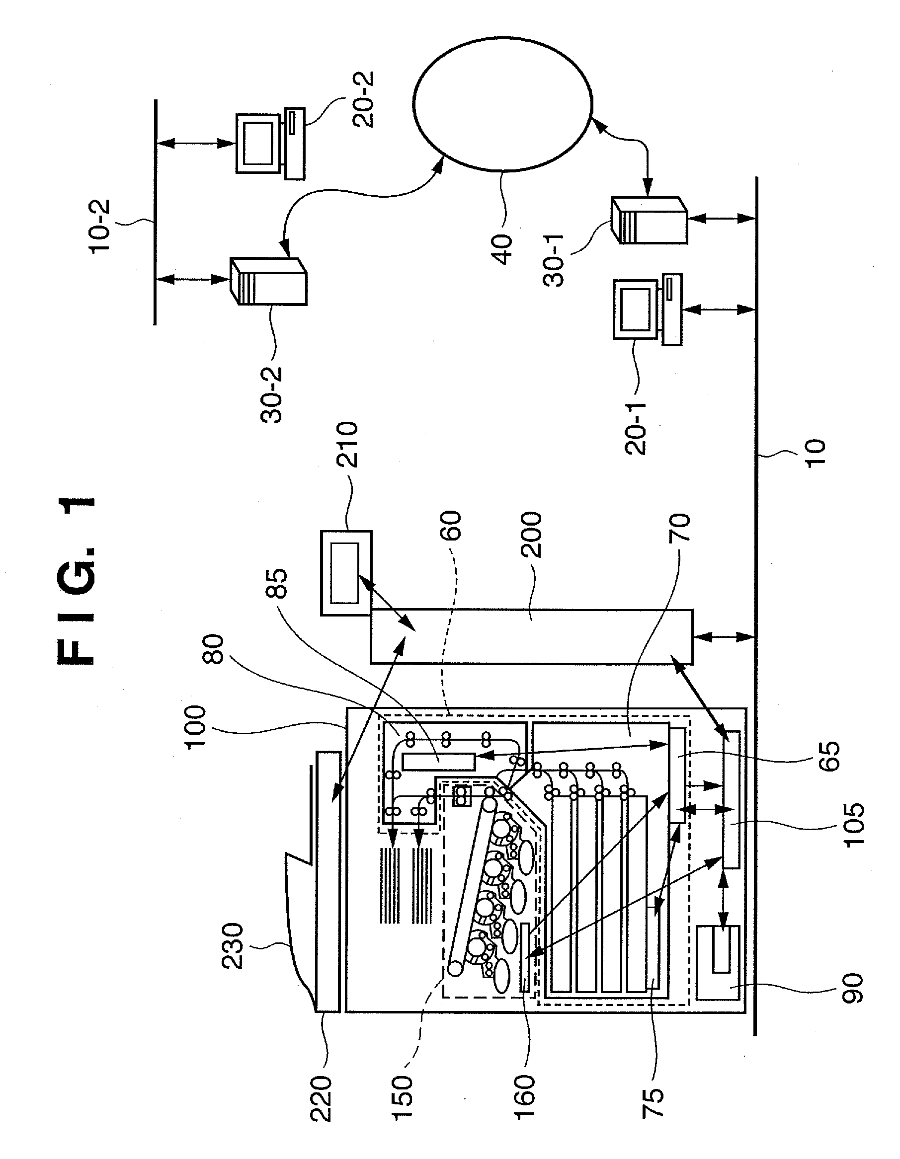
[0086]FIG. 1 is a view showing the overall arrangement of an image forming apparatus according to the first embodiment of the present invention.

[0087] The first embodiment will exemplify, as the image forming apparatus, a multi-functional peripheral (MFP) which comprises an electrophotographic image forming apparatus 100 and functions as a scanner, a facsimile, a copying machine, and a printer for receiving data from a PC and printing it. The image forming apparatus has a color printing function which adopts a photosensitive body and intermediate transfer method.

[0088] The user uses an operation unit 210 to designate a print mode, print count, or print condition, or the serviceman uses the operation unit 210 to make various operation settings in maintenance work. When the user presses a print start key (not shown) on the operation unit 210, a document scanning apparatus 220 and document paper feed apparatus 230 start scanning a document image, and the image forming apparatus start...

second embodiment

[0393] The second embodiment of the present invention will describe registration error correction when a paper conveyance platform 60 comprises registration rollers.

[0394]FIG. 27 is a view showing a concrete positional relationship between paper feed and transfer. This positional relationship is different from that shown in FIG. 25 in the first embodiment in that the registration error amount Px exists between the registration roller and the transfer position.

[0395] As a concrete distance, the distance L(P1) from the paper feed position to the reference position of the paper conveyance platform 60 is 400 mm. The distance L(P2) from the registration roller to the reference position of the paper conveyance platform 60 is 20 mm. The registration error amount Px is 4 mm. The distance L(G2) from the reference position of an image forming subsystem 150 to the transfer position is 100 mm.

[0396] The distance L(P1) from the paper feed position to the reference position of the paper convey...

third embodiment

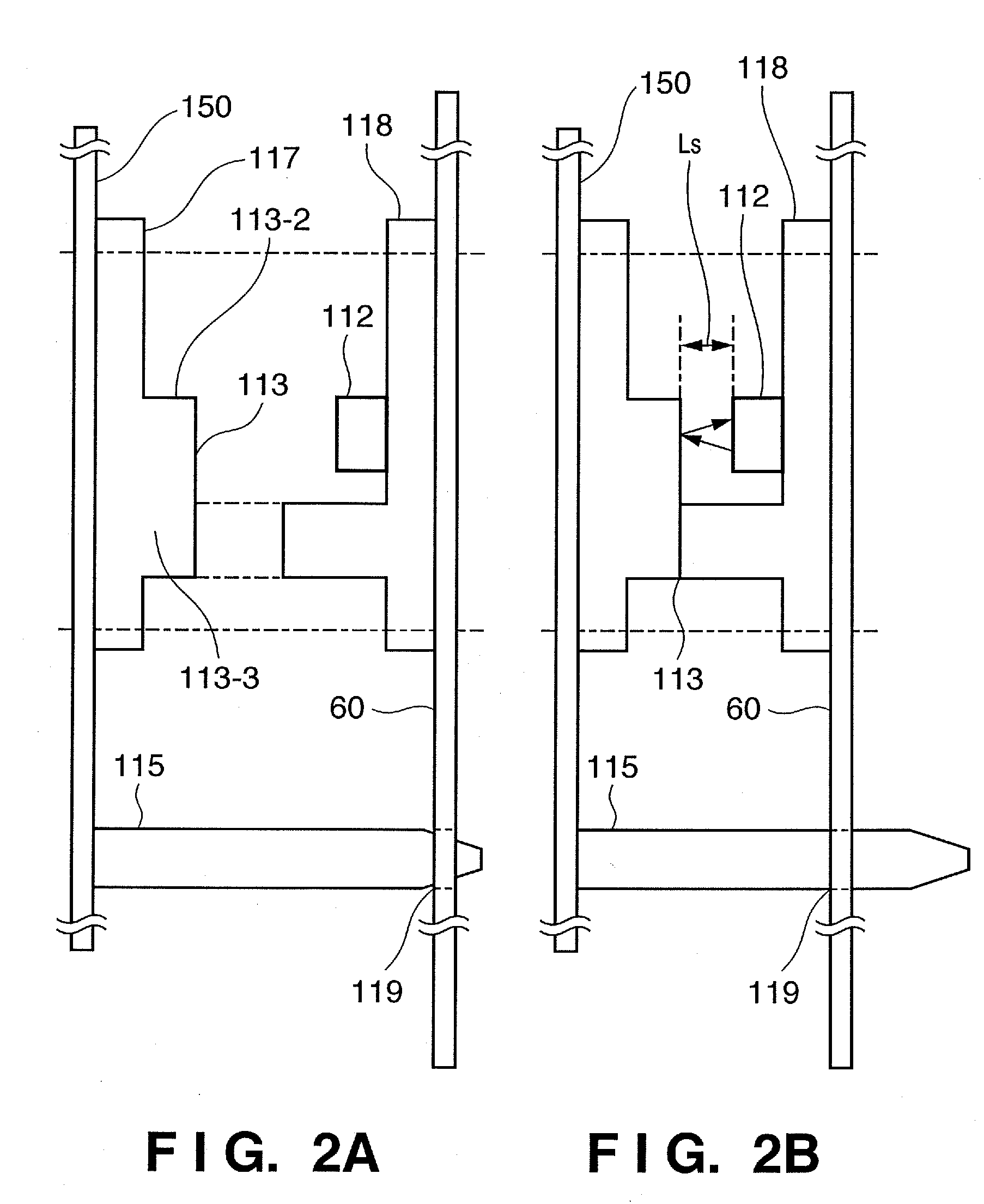
[0412] The third embodiment of the present invention will describe a registration error correction method using a selection unit. The basic arrangement of an image forming apparatus according to the third embodiment is the same as that described in the first embodiment except that an arrangement for calculating a registration error amount does not use the position detector 112.

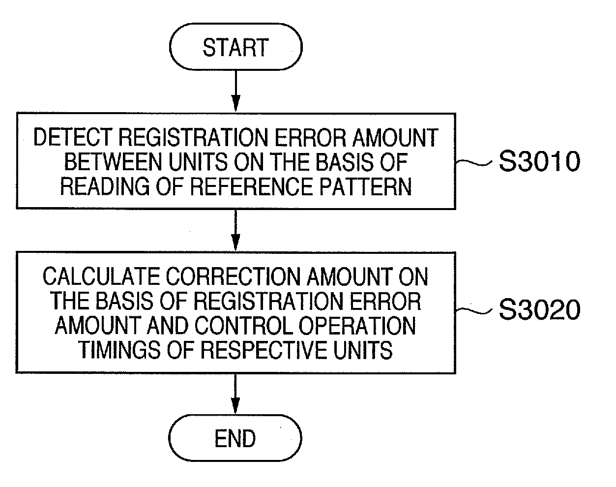
[0413] A flowchart shown in FIG. 31 is executed as an image forming apparatus control method according to the third embodiment.

[0414] A registration error amount between a positioned image forming unit (image forming subsystem 150) and a paper feed conveyance unit (paper conveyance platform 60) is calculated on the basis of the result of an image formed on a recording medium (print result on a registration error correction sheet 1025) (S3110).

[0415] The correction amount is calculated on the basis of the registration error amount calculated in the process of step S3110. The operation timings of the image fo...


PUM


Abstract

An image forming apparatus includes a position detection circuit which detects the registration error amount between a recording medium conveyance unit and an image forming unit positioned by a positioning mechanism, on the basis of reading of a reference pattern arranged on either unit, and a controller which calculates a correction amount on the basis of the detected registration error amount and controls the operation timings of the image forming unit and recording medium conveyance unit in accordance with the correction amount.

Description

BACKGROUND OF THE INVENTION [0001] 1. Field of the Invention [0002] The present invention relates to an image forming apparatus and control method therefor. [0003] 2. Description of the Related Art [0004] There is proposed an apparatus which forms an image by an electrophotographic process of irradiating a photosensitive drum serving as an image carrier with a laser beam or light from a light-emitting element (e.g., LED: Light Emitting Diode) that is modulated in accordance with recording information. [0005] For example, there is proposed a color image forming apparatus having a plurality of image forming units which develop electrostatic latent images formed on photosensitive drums and transfer toner images of respective colors onto a transfer sheet or intermediate transfer belt. [0006] A monochrome image forming apparatus is also proposed which develops an electrostatic latent image formed on one photosensitive drum and transfers a black toner image onto a transfer sheet. [0007] F...

Claims


Application Information

Patent Timeline
IPC IPC(8): G03G15/00
CPCG03G2215/00405G03G15/6564G03G15/235G03G2215/00599
Inventor CHIZAWA, NORIYOSHIOSARI, YOSHIHITOKAWASE, MICHIOOYUMI, MASASHIHATA, SHIGEOOKAMOTO, KIYOSHI
Owner CANON KK
Why Eureka
Try Eureka