Virtual mouse for use in surgical navigation

Inactive Publication Date: 2007-03-29
BIOMET MFG CORP
View PDF99 Cites 250 Cited by
  • Summary
  • Abstract
  • Description
  • Claims
  • Application Information

AI Technical Summary

Benefits of technology

[0009] In exemplary embodiments, the mouse input comprises moving a pointer on the monitor. This is typically accomplished by moving the probe along a substantially flat surface of the pad. In other exemplary embodiments, the probe is moved away from the surface of the pad to make a second mouse input to the computer. This second input could be interpreted by the computer as

Problems solved by technology

The known virtual keypad is limited in the number

Method used


Image

  • Virtual mouse for use in surgical navigation
  • Virtual mouse for use in surgical navigation
  • Virtual mouse for use in surgical navigation

Examples


Embodiment Construction

[0021] The embodiments of the present invention described below are not intended to be exhaustive or to limit the invention to the precise forms disclosed in the following detailed description. Rather, the embodiments are chosen and described so that others skilled in the art may appreciate and understand the principles and practices of the present invention.

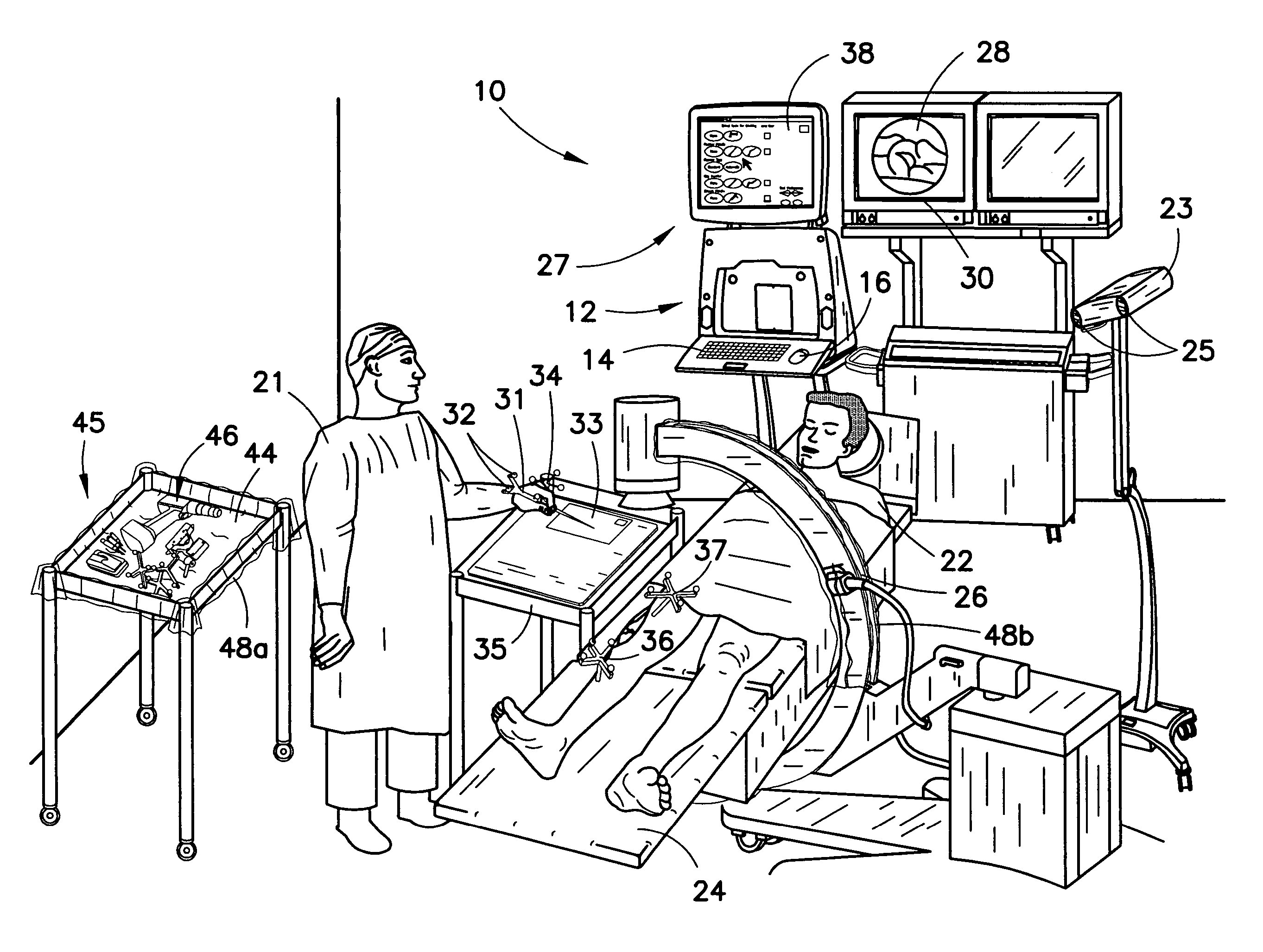
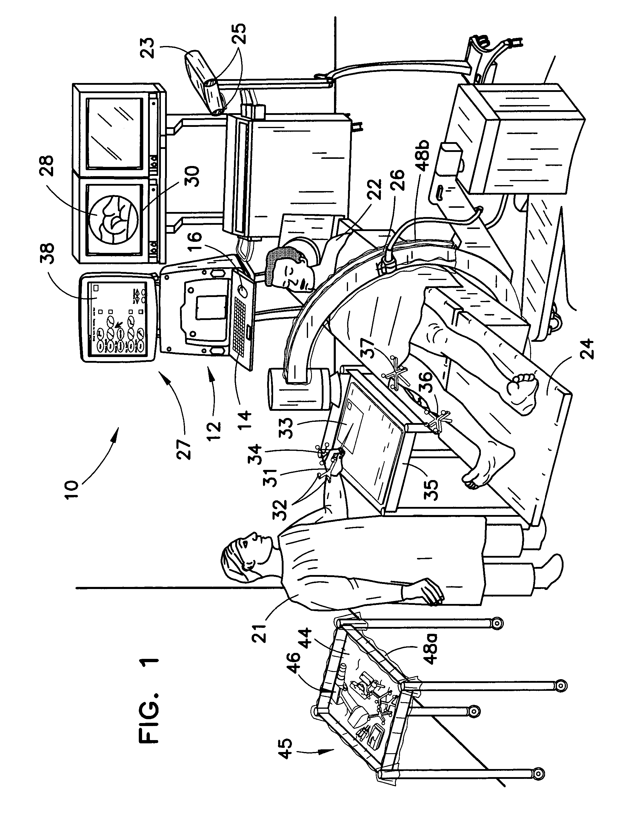
[0022]FIG. 1 shows a perspective view of an operating room with surgical navigation system 10. System 10 may include one or more computers 12 which may be operated by a keyboard 14 and a conventional or physical mouse 16, all of which may be located outside the sterile field. Physician or surgeon 21 is aided by the surgical navigation system in performing knee arthroplasty, also known as knee replacement surgery, on patient 22 shown lying on operating table 24. Surgical navigation system 10 has a tracking system that locates arrays and tracks them in real-time. To accomplish this, the surgical navigation system includes optical...


PUM


Abstract

A surgical navigation system including a computer, a tracking system, and patient anatomical information. The surgical navigation system includes a structure based control system to enable a surgeon to reduce surgery time and costs. A virtual mouse or its functional equivalent is provided to enable a surgeon to access various features of the software based control system.

Description

BACKGROUND [0001] The present invention relates generally to image guided surgery and more particularly to a method of using a computer in an image guided surgery procedure. [0002] Surgical navigation systems, also known as computer assisted surgery and image guided surgery, aid surgeons in locating patient anatomical structures, guiding surgical instruments, and implanting medical devices with a high degree of accuracy. Surgical navigation has been compared to a global positioning system that aids vehicle operators to navigate the earth. A surgical navigation system typically includes a computer, a tracking system, and patient anatomical information. The patient anatomical information can be obtained by using an imaging mode such a fluoroscopy, computer tomography (CT) or by simply defining the location of patient anatomy with the surgical navigation system. Surgical navigation systems can be used for a wide variety of surgeries to improve patient outcomes. [0003] To successfully i...

Claims


Application Information

Patent Timeline
IPC IPC(8): A61B5/05
CPCA61B19/52A61B19/5244A61B2017/00207A61B2019/5268A61B2019/505A61B2019/508A61B2019/5255A61B2019/2269A61B34/20A61B34/74A61B90/36A61B2034/105A61B2034/108A61B2034/2055A61B2034/2068
Inventor SCHOENEFELD, RYAN J.
Owner BIOMET MFG CORP
Why Eureka
Try Eureka