Endotracheal electrode and optical positioning device

a technology of optical positioning and trachea, which is applied in the direction of respirator, diagnostic recording/measuring, application, etc., can solve the problems of hematoma, constant risk of abscess or hematoma of the larynx, and method that requires considerable skill and skill, and the possibility of hematoma

Inactive Publication Date: 2007-04-05
REA JAMES LEE
View PDF1 Cites 34 Cited by
  • Summary
  • Abstract
  • Description
  • Claims
  • Application Information

AI Technical Summary

Benefits of technology

[0017] This invention is an endotracheal electrode and optical positioning device that attaches to an endotracheal tube for insertion into the glottic chink (area between the human true vocal cords) to provide a platform for a laryngeal surface electrode(s) and for receiving a flexible fiber optic laryng...

Problems solved by technology

This method requires considerable skill and carries the constant risk of abscess or hematoma of the larynx.
This method has fewer drawbacks than the direct laryngoscope approach but still requires considerable practice and skill in electrode placement.
Again, since the procedure is nonvisual the possibility of hematoma, abscess, misplacement, or needle breakage is present.
There is a learning curve for placement of endotracheal tube electrodes, with misplacement causing annoying delay of the procedure in order to correct the problem, or suspension of the use of EEMG.
The endotracheal tube borne electrode can be difficult to position and maintain for monitoring purposes, leading to a substantial percentage of uses with failure to monitor.
Needle electrodes may be intrinsically more reliable for monitoring purposes but the blind puncture of the vocal cord from above inevitably leads to hematoma and possible abscess of the vocal cord with corresponding morbidity for the patient.
The basic problem with laryngeal surface electrodes is that the aperture created by the human glottis is triangular and the endotracheal tube is round.
This creates a fundamental mismatch between th...

Method used


Image

  • Endotracheal electrode and optical positioning device
  • Endotracheal electrode and optical positioning device
  • Endotracheal electrode and optical positioning device

Examples


Embodiment Construction

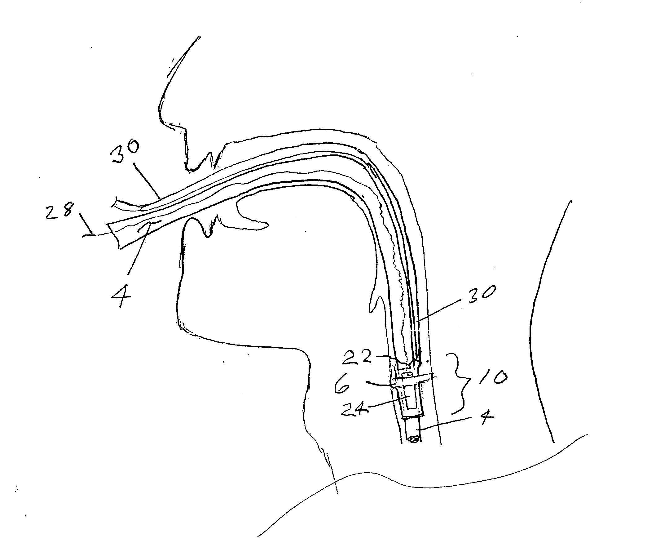
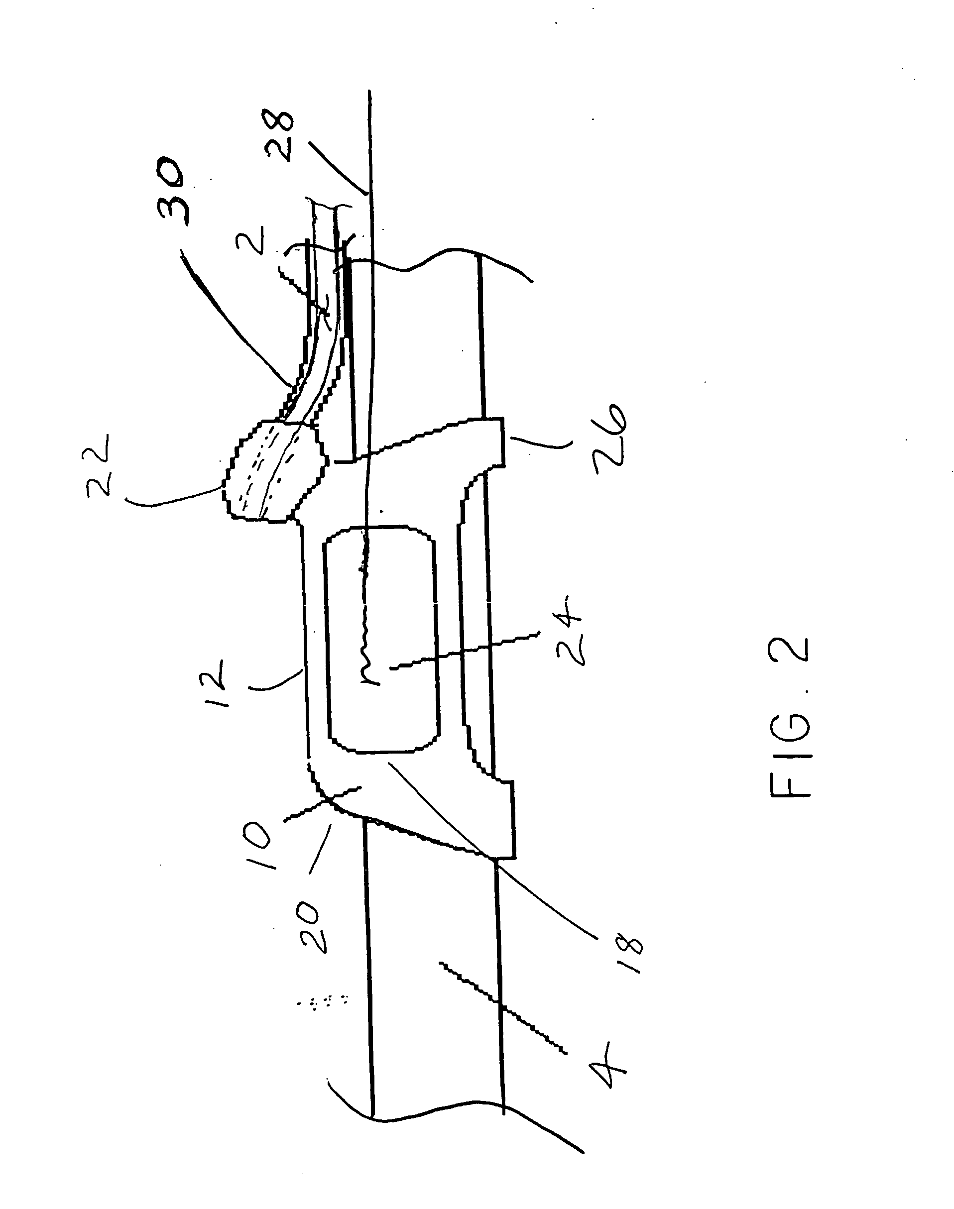
[0028] Referring now to the drawings, there is shown the preferred embodiment of the endotracheal electrode and optical positioning device 10 of this invention for carrying and positioning laryngeal surface electrode(s) 24 and for receiving a fiber optic video device 2 for continuous monitoring of the larynx. The preferred embodiment and the best mode contemplated of the endotracheal electrode and optical positioning device 10 of the present invention are herein described. However, it should be understood that the best mode for carrying out the invention hereinafter described is offered by way of illustration and not by the way of limitation. It is intended that the scope of the invention include all modifications that incorporate its principal design features.

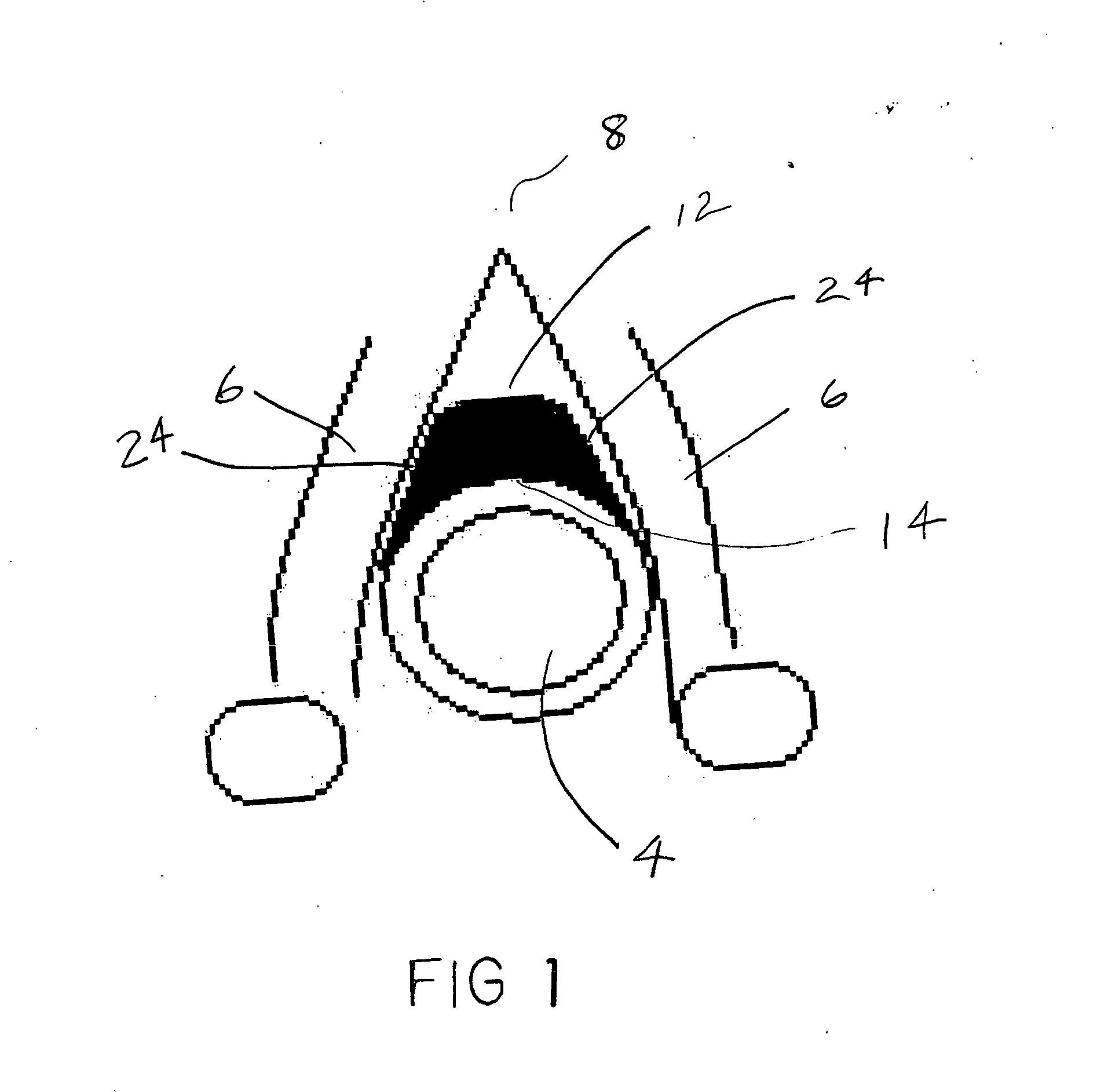
[0029] The endotracheal electrode and optical positioning device 10 of this invention is inserted into the glottic chink between the human true vocal cords 6, as shown on FIGS. 1 and 4. It provides a platform for a laryngeal ...


PUM


Abstract

An endotracheal electrode and optical positioning device usable in conjunction with an endotracheal tube having a short elongated triangular shaped body with a superior surface that projects towards the junction of the vocal cords, a posterior surface that projects towards the endotracheal tube or the posterior-interior surface of the cricoid cartilage, and generally straight right and left lateral surfaces that project anterior lateral on either side toward the vocal cords. The lateral surfaces are of appropriate dimensions for attachment of laryngeal surface electrodes. The body has a center opening or channel that wraps around, slides over, or otherwise attaches to an endotracheal tube or to a ventilatory apparatus. A docking recess on the proximal aspect of the superior surface is used for receiving a fiberoptic laryngoscope or a positioning rod. A tube is attachable to the docking recess and extends outward in conjunction with the endotracheal tube for insertion of the fiberoptic laryngoscope.

Description

BACKGROUND OF THE INVENTION [0001] The present invention relates to an endotracheal positioning device and more specifically a positioning device that provides optimal positioning of a surface electrode against the vocal cord muscles for laryngeal surgical electromyographic monitoring and positioning a fiberoptic laryngoscope for visual monitoring. [0002] This is a continuation in part of application Ser. No. 11 / 129,593, entitled Endotracheal Positioning Device, by Rea, now abandoned. [0003] There are several electrode systems that have been advocated for laryngeal evoked electromyographic (EMG) for recurrent and external nerve preservation. They are classified as invasive (needle) or noninvasive (surface) electrodes. [0004] The advantages of needle electrodes are more precise localization of the EMG sample to the needle tip, and possible enhanced security of the electrode-muscle connection. Simple needle electrodes, and fine-wire or hook-wire electrodes have been used in the glotti...

Claims


Application Information

Patent Timeline
IPC IPC(8): A62B9/06
CPCA61B1/267A61B5/04886A61M16/04A61M16/0488A61M2230/08A61B5/394
Inventor REA, JAMES LEE
Owner REA JAMES LEE
Why Eureka
Try Eureka