Rotary pull switch

a rotary pull switch and pull switch technology, applied in the direction of instruments, electrical appliances, controlling members, etc., to achieve the effect of small wear and low construction

Inactive Publication Date: 2007-04-05
DELPHI TECH INC
View PDF16 Cites 15 Cited by
  • Summary
  • Abstract
  • Description
  • Claims
  • Application Information

AI Technical Summary

Benefits of technology

[0007] On account of these measures, there is provided a rotary/pull switch which contactlessly detects the different switching positions of the actuating element and which, with a cheap construction, is subjected to little wear. ...

Problems solved by technology

This motor vehicle light switch comprises several mechanical switching members with contact elements for acting on term...

Method used


Image

  • Rotary pull switch
  • Rotary pull switch
  • Rotary pull switch

Examples


Embodiment Construction

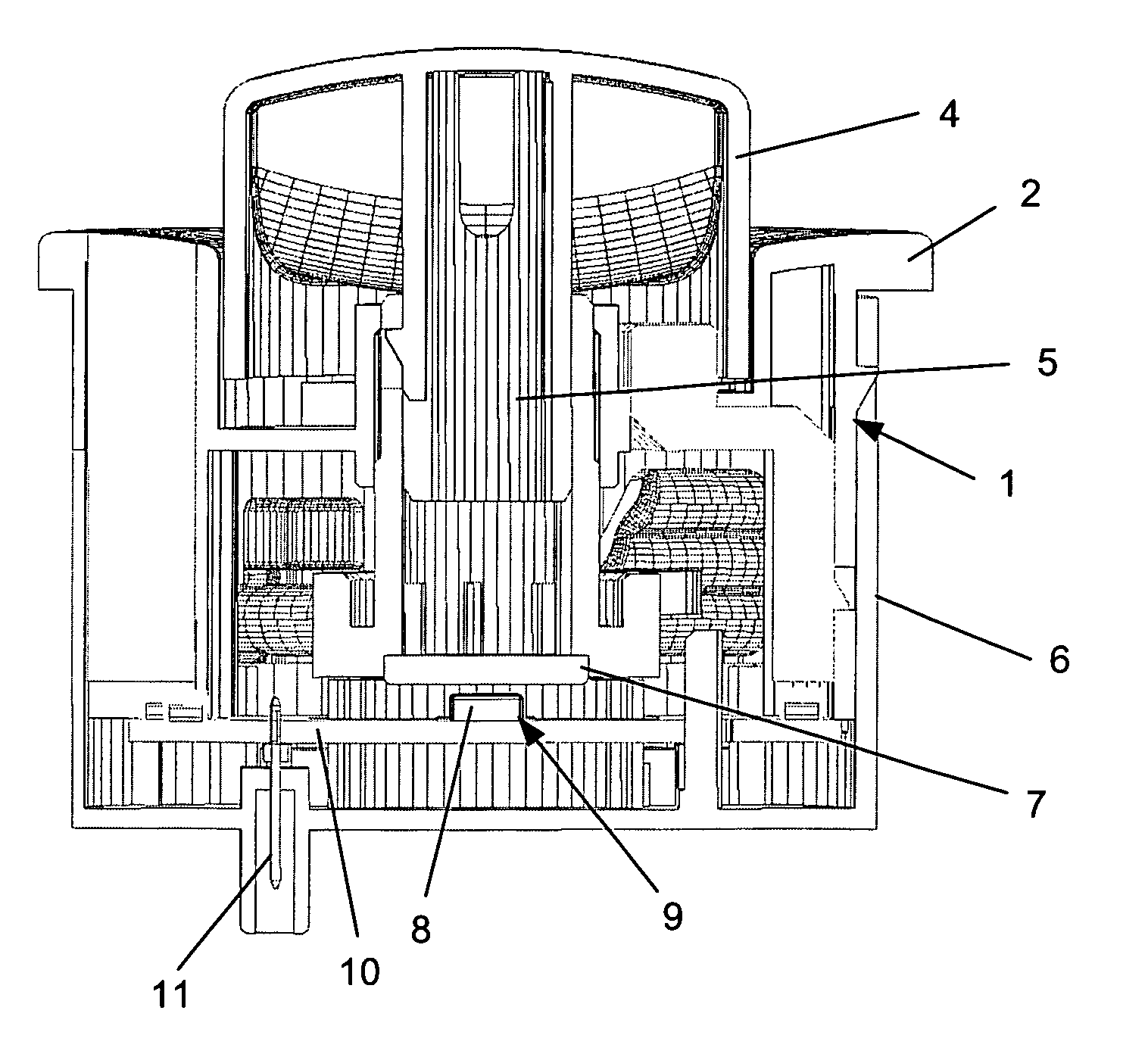
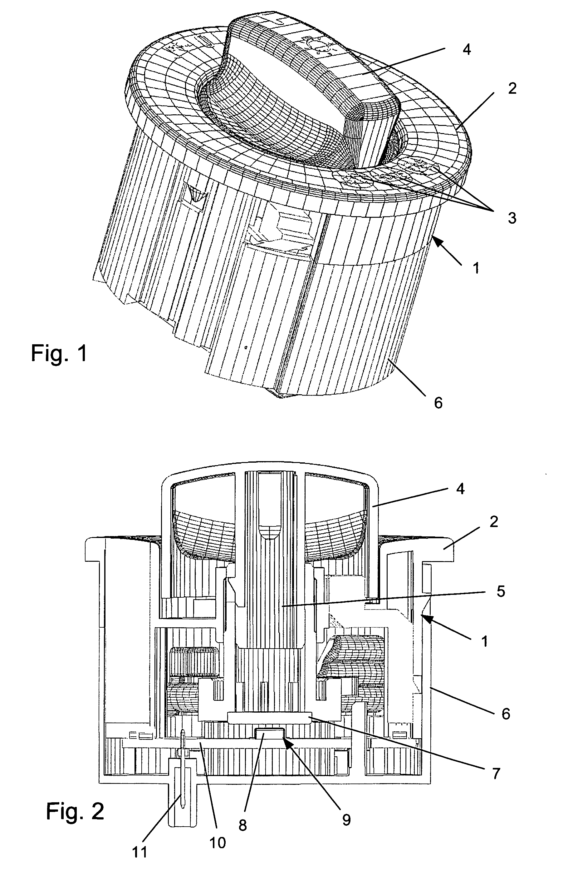
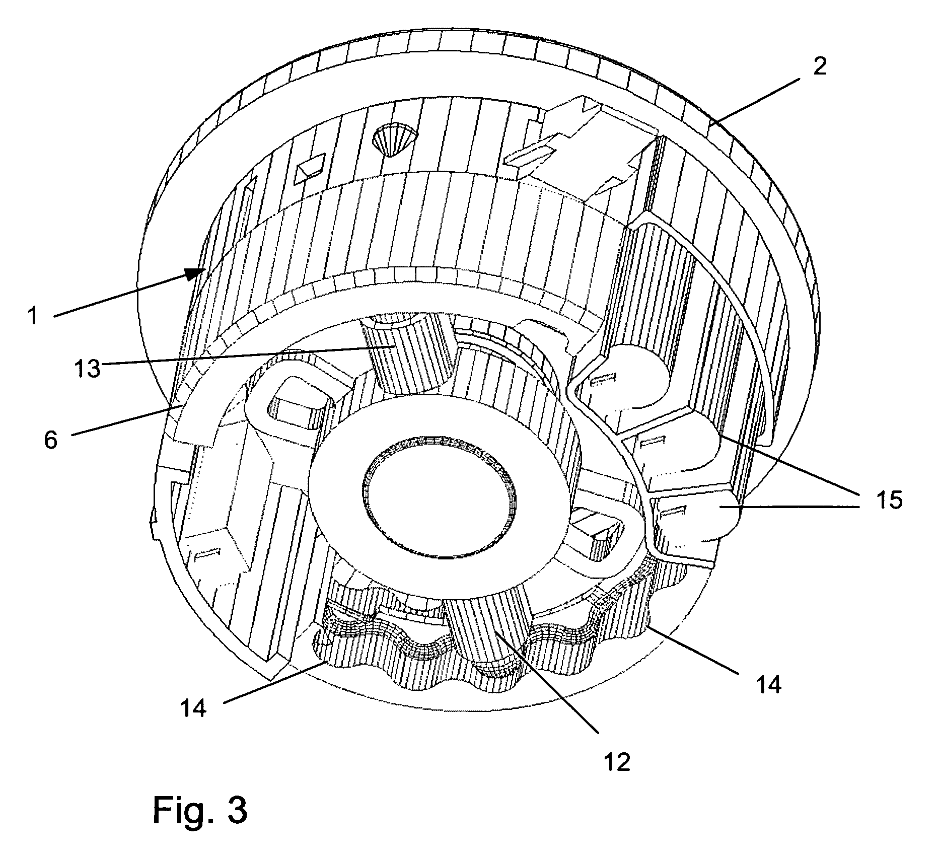
[0020] In an exemplary embodiment, a rotary / pull switch includes a housing 1 with a cover 2 at the top that comprises several backlightable symbols 3, and through which extends an actuating element 4 that, on its lower side, is provided with an axle 5 mounted rotatably and axially displaceably in the housing 1. At the free end of the axle 5, facing in the direction of a base 6, is arranged a permanent magnet 7 that co-operates with two Hall sensors 9 that are combined into a unit 8 and oriented with an offset of 90° from each other in order to detect the different switching positions of the actuating element 4, which can be acted upon by rotation and pulling.

[0021] The Hall sensors 9 are coupled to an electrical system of a motor vehicle by integrated strip conductors 10 and terminal contacts 11 in the base 6. Due to the arrangement of the Hall sensors 9 offset by 90°, on rotation of the actuating element 4, which is coupled by the axle 5 to the permanent magnet 7, a sine-like or c...


PUM


Abstract

A rotary/pull switch , in particular a light switch for a motor vehicle, includes an actuating element having a base and axle that is guided in a housing. A permanent magnet is associated with the axle and several magnetic field sensors are associated with the base for determining the switching positions of the actuating element.

Description

TECHNICAL FIELD [0001] The invention relates to a rotary / pull switch, in particular a light switch, for a motor vehicle, with an actuating element having an axle which is guided in a housing, and with a base. BACKGROUND [0002] DE 199 29 200 A1 discloses a rotary selector switch system which includes a rotatably mounted shaft and a permanent magnet which is rotatable relative to a magnetoresistive sensor upon movement of the shaft. The rotary movement of the shaft is transmitted to a rotatably mounted element, in which is embedded the permanent magnet, and which is mounted rotatably within range of the magnetoresistive sensor. The axis of rotation of the shaft differs from the axis of rotation of the permanent magnet. [0003] Furthermore, DE 199 53 204 A1 shows a switching module for switching control current paths, in particular in vehicles, with a switching module housing, with an actuating unit that can be actuated in particular by a human being, and with a switching member that is...

Claims


Application Information

Patent Timeline
IPC IPC(8): H01H9/00
CPCG05G1/02G05G1/10H03K17/97H03K2217/94068
Inventor KOEHLER, JOACHIMLENG, PETERSCHNELL, KLAUS
Owner DELPHI TECH INC
Why Eureka
Try Eureka