Surgical stapling device

a stapling device and surgical technology, applied in the direction of surgical staples, surgical forceps, applications, etc., can solve the problems of difficult to view indicia, and achieve the effect of preventing the rattling of the pivotable trigger

Active Publication Date: 2007-04-05
TYCO HEALTHCARE GRP LP
View PDF99 Cites 55 Cited by
  • Summary
  • Abstract
  • Description
  • Claims
  • Application Information

AI Technical Summary

Benefits of technology

[0011] In one embodiment, the anvil center rod includes a plurality of flexible arms which are positioned to flex over and engage an annular protrusion formed about the anvil retainer. The shell assembly can include an inner guide portion having a rigid bushing dimensioned to slidably receive the engaged portions of the anvil center rod and the anvil retainer. The rigid bushing is dimensioned to provide lateral support for the flexible arms of the anvil center rod to prevent disengagement of the anvil center rod from the anvil retainer.
[0013] In one embodiment, the surgical stapling device includes a pivotable trigger lock supported on the handle assembly. The pivotable trigger lock is movable from a first position to prevent actuation of the firing trigger to a second position to permit actuation of the firing trigger. The firing trigger can include a pivotable member. The pivotable member includes first and second spaced abutments. A tip of the pivotable trigger lock is positioned between the spaced abutments when the pivotable trigger lock is in its first position. In one embodiment, the tip of the pivotable trigger lock includes a flexible tab which is positioned to engage the pivotable member between the spaced abutments to prevent rattling of the pivotable trigger between the spaced abutments.

Problems solved by technology

Such indicia is sometimes difficult to view.

Method used


Image

  • Surgical stapling device
  • Surgical stapling device
  • Surgical stapling device

Examples


Embodiment Construction

[0080] Preferred embodiments of the presently disclosed surgical stapling device will now be described in detail with reference to the drawings in which like reference numerals designate identical or corresponding elements in each of the several views.

[0081] Throughout this description, the term “proximal” will refer to the portion of the instrument closest to the operator and the term “distal” will refer to the portion of the instrument furthest from the operator.

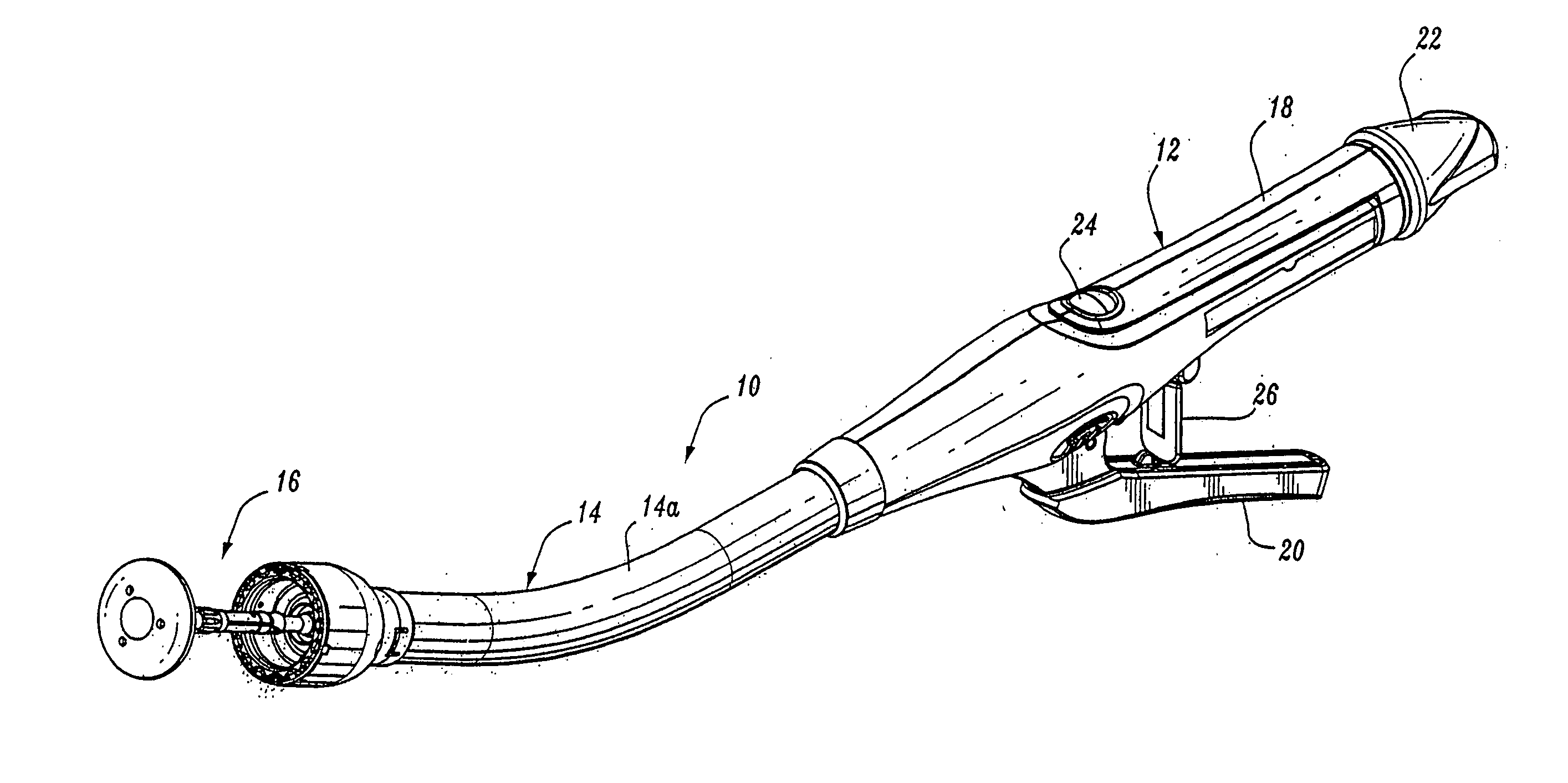
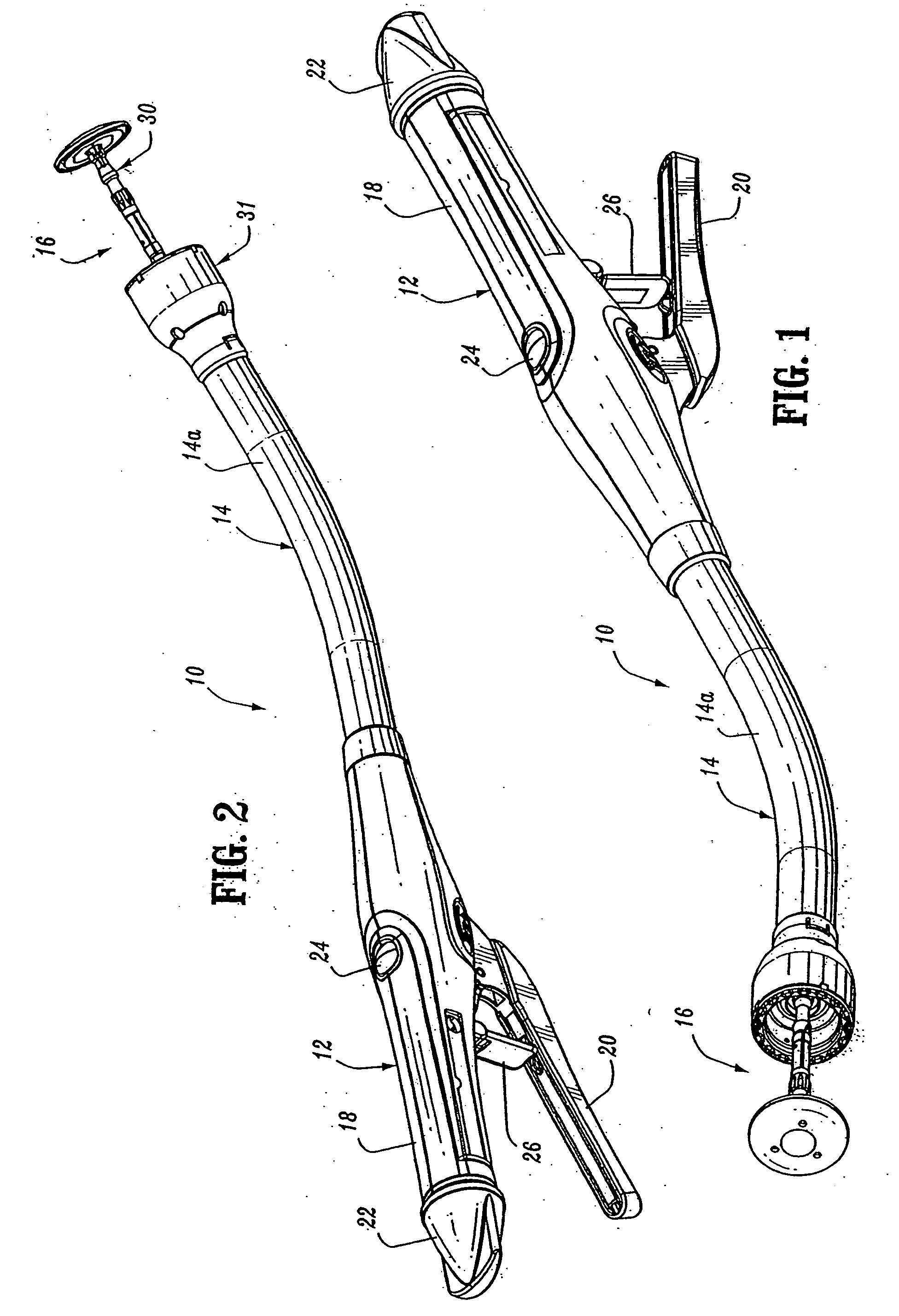
[0082]FIGS. 1 and 2 illustrate one preferred embodiment of the presently disclosed surgical stapling device shown generally as 10. Briefly, surgical stapling device 10 includes a proximal handle assembly 12, an elongated central body portion 14 including a curved elongated outer tube 14a, and a distal head portion 16. Alternately, in some surgical procedures, e.g., the treatment of hemorrhoids, it is desirable to have a substantially straight, preferably shortened, central body portion. The length, shape and / or the diame...


PUM

PropertyMeasurementUnit
flexibleaaaaaaaaaa
rotationaaaaaaaaaa
distanceaaaaaaaaaa

Abstract

A surgical stapling device is disclosed for performing circular anastomoses. The surgical stapling device includes a handle portion, an elongated body portion and a head portion including an anvil assembly and a shell assembly. The head portion includes an anvil assembly including a tiltable anvil which will tilt automatically after the device has been fired and unapproximated. The tiltable anvil provides a reduced anvil profile to reduce trauma during removal of the device after the anastomoses procedure has been performed. The stapling device includes an approximation mechanism including a rotatable knob, a screw having a helical channel and an anvil retainer. The helical channel includes a dwell portion for providing a tactile indication to a surgeon that the anvil retainer has been advanced to a position wherein the anvil assembly can be removed from the anvil retainer. A removable trocar for attachment to the anvil assembly is also disclosed which includes a rib positioned proximally of a mounting projection. The rib is positioned to align the mounting projection with associated engagement structure of the anvil assembly.

Description

[0001] This application claims priority from U.S. provisional Patent Application No. 60 / 714,141, filed Sep. 2, 2005 which claims priority from U.S. patent application Ser. No. 10 / 528,975, filed Mar. 23, 2005 which claims priority to PCT Application Serial No. PCT / US03 / 31638, filed Oct. 6, 2003 which claims priority from U.S. Provisional Application Ser. No. 60 / 416,055, filed Oct. 4, 2002, the entire contents of all of which being incorporated by reference herein.BACKGROUND [0002] 1. Technical Field [0003] The present disclosure relates generally to a surgical stapling device for applying surgical staples to body tissue. More particularly, the present disclosure relates to a surgical stapling device suitable for performing circular anastomosis of hollow tissue organs. [0004] 2. Background to Related Art [0005] Anastomosis is the surgical joining of separate hollow organ sections. Typically, an anastomosis procedure follows surgery in which a diseased or defective section of hollow ti...

Claims


Application Information

Patent Timeline
Patent Type & Authority Applications(United States)
IPC IPC(8): A61B17/04A61B17/115A61B17/28A61B19/00
CPCA61B2019/4857A61B17/068A61B2017/2905A61B2019/5219A61B17/32053A61B2017/07257A61B2017/00371A61B17/115A61B17/1155A61B2090/0811A61B2090/3616
Inventor MILLIMAN, KEITH L.JANKOWSKI, BRUCE K.CUNY, DOUGLAS J.SNIFFIN, KEVINDATO, ANTHONYGRESHAM, RICHARD D.
Owner TYCO HEALTHCARE GRP LP
Why Eureka
Try Eureka