
Panel fixing structure

a technology for fixing structures and panels, applied in the direction of electrical equipment, substation/switching arrangement details, casings/cabinets/drawer details, etc., can solve the problems of time waste, screw failure, and inconvenient operation, so as to increase the cost of screws, fast and convenient implementation, and save time

Inactive Publication Date: 2007-04-05
INVENTEC CORP
View PDF16 Cites 0 Cited by
  • Summary
  • Abstract
  • Description
  • Claims
  • Application Information

AI Technical Summary

Benefits of technology

[0010] In light of the foregoing drawbacks of the prior art, it is an objective of the present invention to provide a panel fixing structure, which allows a panel to be assembled to or disassembled from an electronic device without the use of any tool.
[0011] It is another objective of the present invention to provide a panel fixing structure, which allows assembly and disassembly of the panel to be quickly and conveniently performed.
[0012] It is a further objective of the present invention to provide a panel fixing structure without having to alter inherent components or design of the electronic device.
[0015] The second fixing portion of each of the two side plates has a protuberant structure. Preferably, the protuberant structure is a protruding block or a protruding rib. The protuberant structure of the second fixing portion of one of the side plates can be a right-angled protuberant structure or a hook structure, and the protuberant structure of the second fixing portion of the other side plate can be a structure having a round chamfer or an arc structure, so as to facilitate assembly / disassembly of the panel to / from the electronic device.
[0017] By the use of the panel fixing structure of the present invention, assembly and disassembly of the panel to and from the electronic device can be performed without any tool, thereby overcoming the prior-art drawbacks such as inconvenience in operation caused by using screws to fix the panel to the electronic device and the need of auxiliary tools for assembly and disassembly of the panel, such that the present invention can avoid prior-art problems such that loss of screws, inefficient assembly and disassembly, waste of time and increase in cost for screws.
[0018] Moreover, as disassembly and assembly of the panel are performed without any tool when using the panel fixing structure of the present invention, the assembly and disassembly process can be quickly and conveniently implemented. Further, the use of the panel fixing structure of the present invention does not alter inherent components or design of the electronic device. Therefore, the present invention improves the convenience and efficiency of assembling or disassembling the panel to or from the electronic device, such that the panel fixing structure of the present invention can be widely applied to current electronic products.

Problems solved by technology

However, by the above fixing method using the screws, auxiliary tools are required for disassembly and assembly of the panel from and to the electronic device, thereby causing inconvenience and constraint on operation.
However, the screws for assembling the panel to the server may easily drop into the cabinet or become lost due to the limited surrounding space.
This makes the disassembly and assembly process not performed efficiently, causes a waste of time and increases the extra cost for screws.
In addition, there is no panel fixing technology for disassembling and assembling the panel without the use of auxiliary tools and without altering the inherent components or design of the electronic device.

Method used


Image

  • Panel fixing structure
  • Panel fixing structure
  • Panel fixing structure

Examples


Embodiment Construction

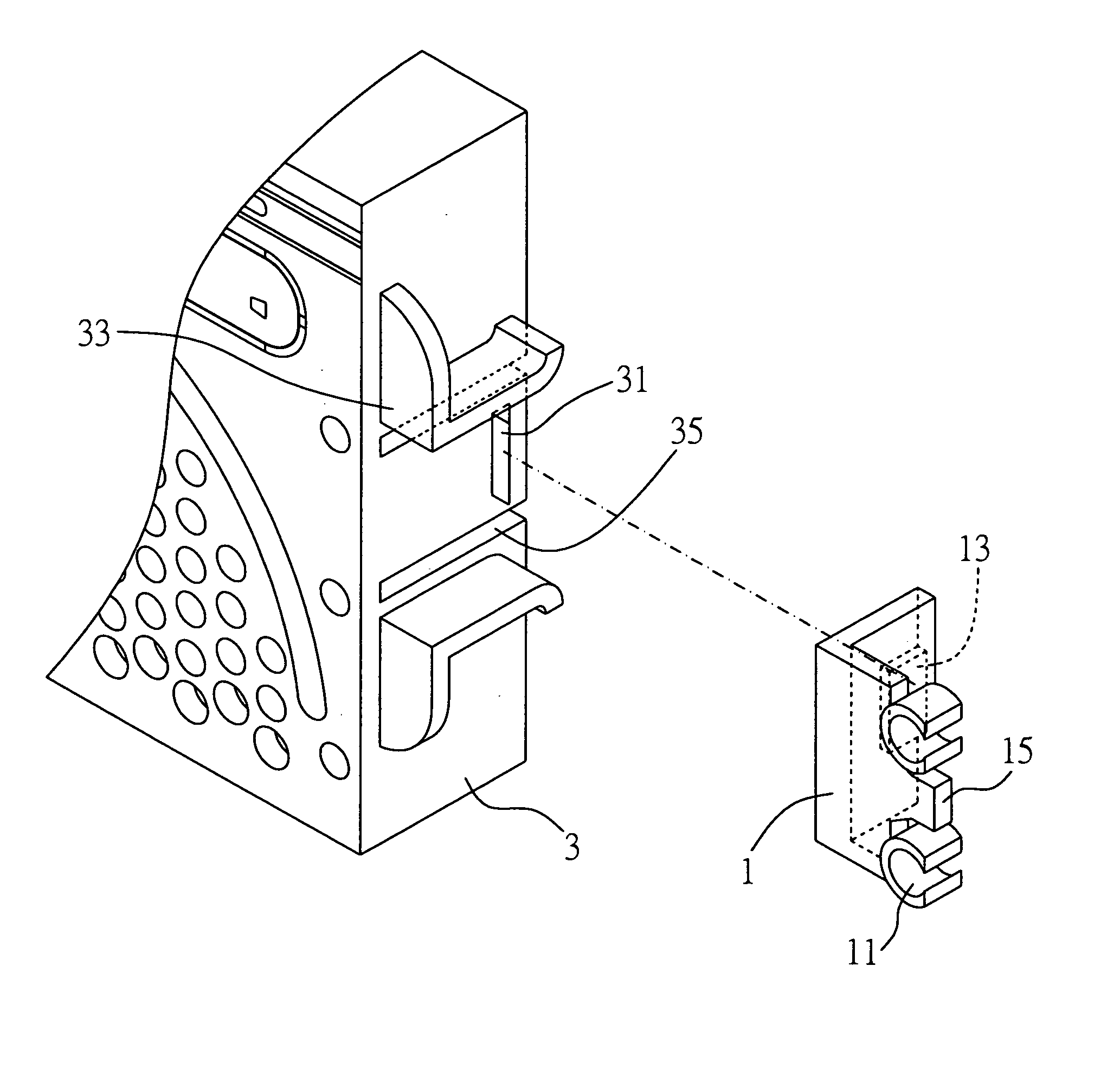
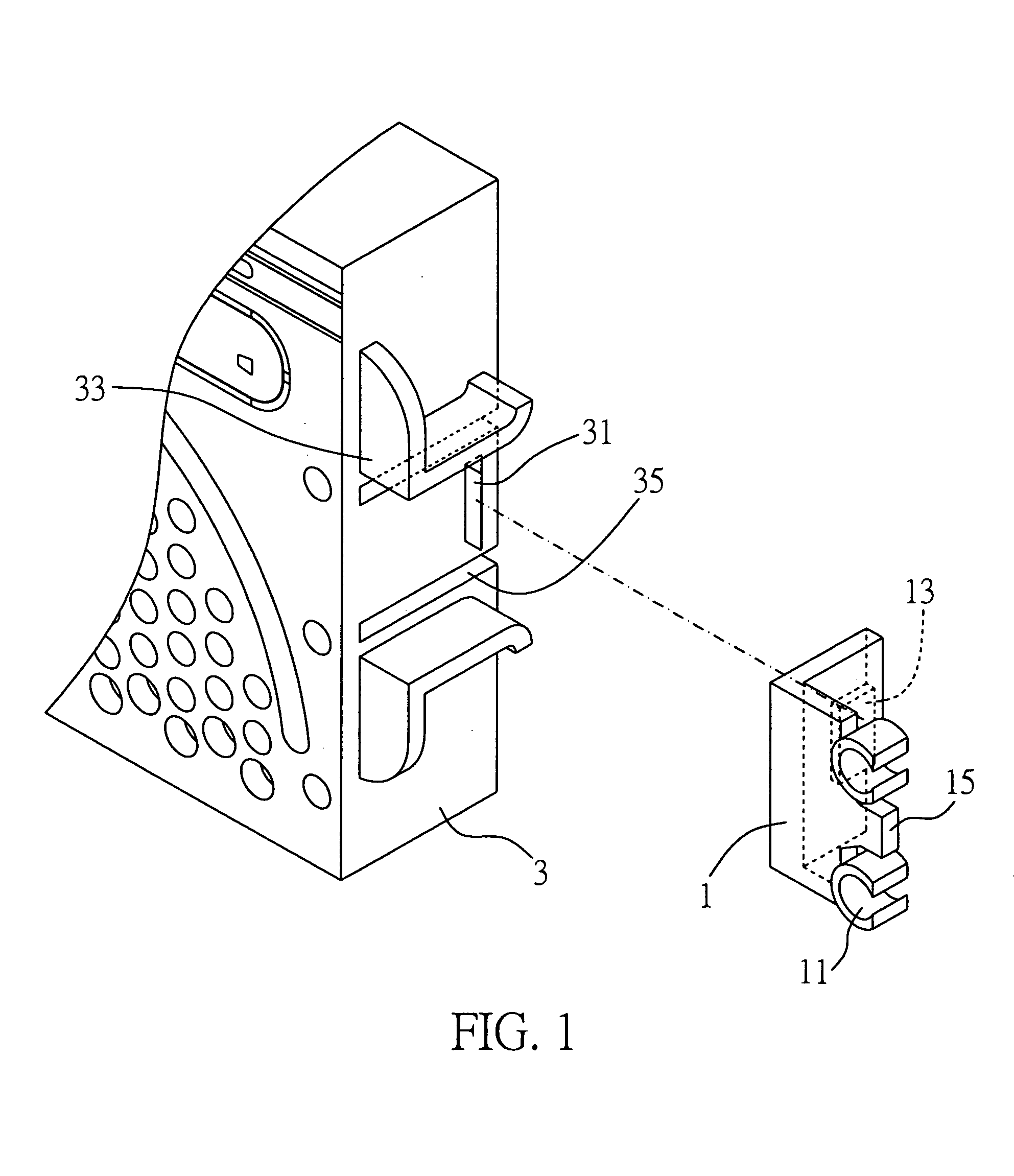
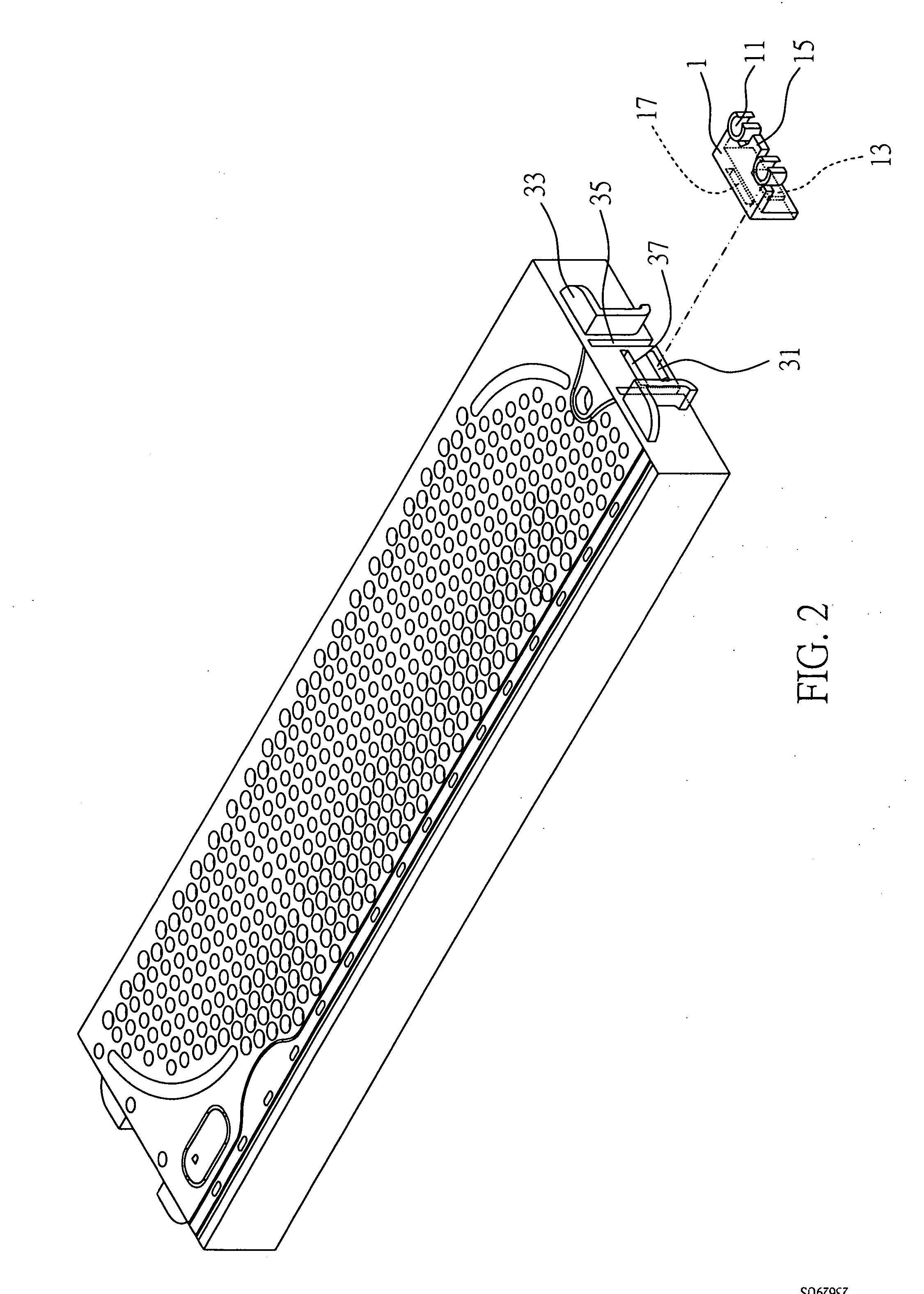
[0024] FIGS. 1 to 4G are schematic diagrams of a panel fixing structure according to a preferred embodiment of the present invention. It should be noted that the panel fixing structure is used to fix a panel to an electronic device. The electronic device can be, but not limited to, a server, and other conventional electronic devices are also suitably used in the present invention. Since the structure of the electronic device would not be changed in the present invention, only the part of structure of the electronic device directly relating to the present invention is shown in the drawings for the sake of simplicity.

[0025] Moreover, the drawings are all simplified schematic diagrams and merely show the components or elements relating to the present invention. It should be understood that the arrangement of components or elements could be more complex in practice.

[0026] As shown in FIGS. 1 and 2, the panel fixing structure in this embodiment of the present invention comprises two ho...


PUM


Abstract

A panel fixing structure is proposed, for fixing a panel to an electronic device having fixing sections on two sides thereof respectively. The structure includes two holding members and two side plates. Each of the holding members includes a first fixing portion and at least one coupling portion that is for being coupled to at least one of the fixing sections. The two side plates are provided on two sides of the panel respectively. Each of the side plates includes a second fixing portion for being coupled to the first fixing portion. Therefore, assembly and disassembly of a panel for the electronic device can be performed by means of the panel fixing structure without using any tool.

Description

BACKGROUND OF THE INVENTION [0001] 1. Field of the Invention [0002] The present invention relates to panel fixing structures, and more particularly, to a panel fixing structure for fixing a panel to an electronic device. [0003] 2. Description of the Background Art [0004] A common structural design of an electronic device, such as a server, a computer or the like includes a housing or panel to protect inner circuit components or mechanism components of the electronic device from damage or dust and provide a desirable appearance of the electronic device. For example of the server, there are provided fixing sections such as handles on two sides thereof to facilitate maintenance, testing or manipulation of the server. [0005] Generally the panel is assembled and fixed to the electronic device by means of screws, and is locked to the electronic device by inserting a locking member with a locking piece into the panel. The related patent includes Taiwanese Utility Model Patent No. M248203. ...

Claims


Application Information

Patent Timeline
IPC IPC(8): H02B1/00
CPCH05K5/03
Inventor KAO, KUANG-YI
Owner INVENTEC CORP
Learn More