
Method of fabricating a release substrate

a technology of release substrate and release layer, which is applied in the direction of lamination ancillary operations, electrical equipment, chemistry apparatus and processes, etc., can solve the problems of difficult to release the substrate when desired, and the problem of problematic release, so as to facilitate the release of the substrate release rate and facilitate the release of the substrate release layer

Active Publication Date: 2007-04-05
S O I TEC SILICON ON INSULATOR THECHNOLOGIES
View PDF9 Cites 0 Cited by
  • Summary
  • Abstract
  • Description
  • Claims
  • Application Information

AI Technical Summary

Benefits of technology

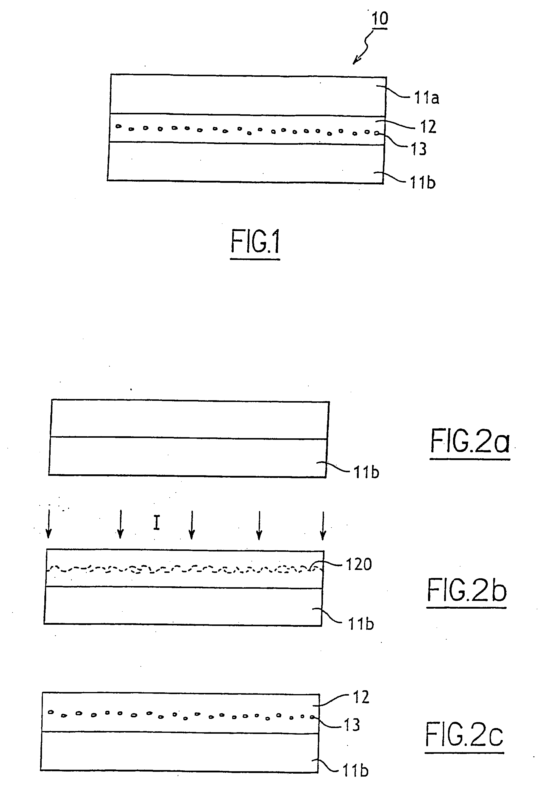
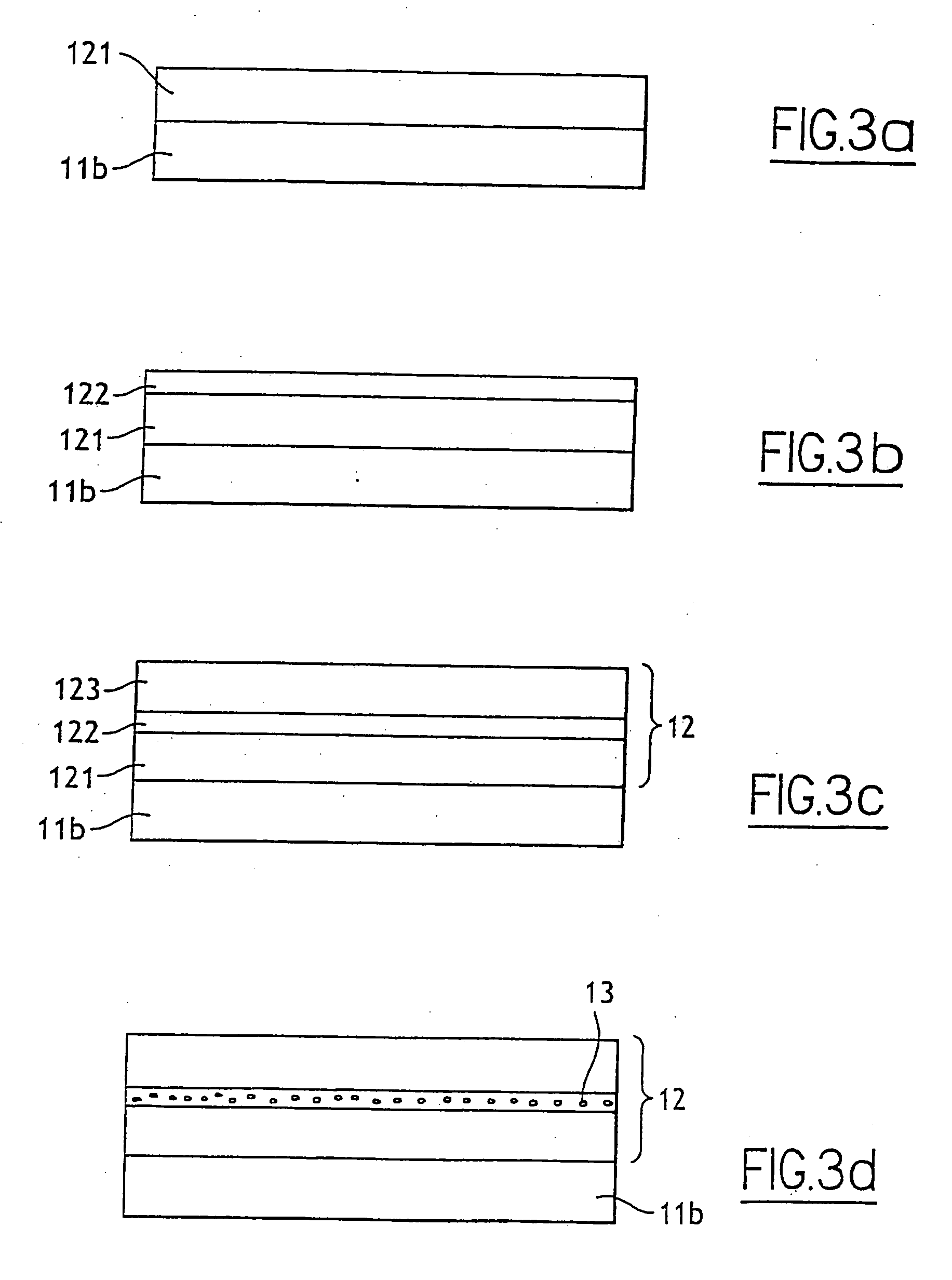
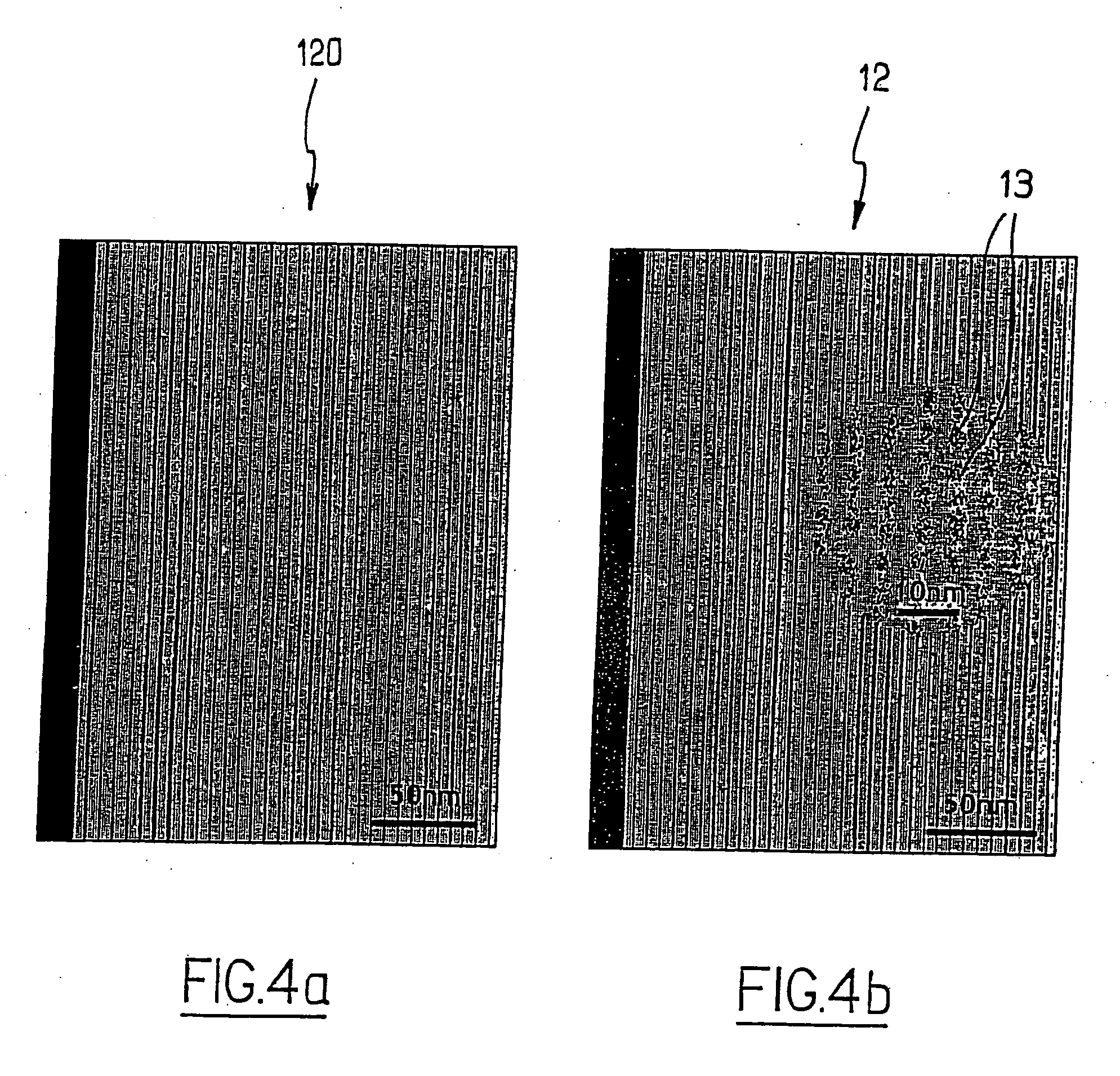
[0010] The present invention now provides for the production of release substrates which, prior to releasing, can undergo treatments (for example, anneal type heat treatments) without substantially affecting the energy of the reversible connection of the release substrate. In particular, the invention provides a method of fabricating a release substrate of semiconductor materials, by forming a reversible connection between two substrate release layers by providing a connecting layer of a first material, and providing a concentrated zone of nanoparticles of a second material in the connecting layer to facilitate release of the substrate release layers. With this method, the connecting layer has a bonding energy that is substantially constant even when the release substrate is exposed to heat treatments to facilitate the release of the substrate release rates when desired and not at other times.

Problems solved by technology

One problem which arises with such release substrates is that any treatments (in particular heat treatments) which are to be carried out on the release substrate prior to release may compromise the reversible nature of the “release” bond of the substrate, rendering release problematical.
Certain heat treatments can weaken the bond so that release occurs when not desired, while others can actually strengthen the bond making it more difficult to release the substrates when desired.
In general, applying an anneal type heat treatment to release substrates having a reversible connection that has been formed using any technique (bonding, and other techniques—for example, creating a porous region, etc) risks modifying the energy associated with the reversible connection of the substrate so that release does not occur when desired.

Method used


Image

  • Method of fabricating a release substrate
  • Method of fabricating a release substrate
  • Method of fabricating a release substrate

Examples


Embodiment Construction

[0018] The invention thus provides a method which specifically aims at fabricating a release substrate comprising two layers connected through a reversible connection. This method preferably comprises forming the reversible connection by a connecting layer obtained from a first material, with the connecting layer further comprising a concentrating zone of nanoparticles of a second material disposed to facilitate release of the substrate. The first and second materials are selected to maintain the energy associated with the reversible connection substantially constant even when the substrate is exposed to heat treatment to facilitate release.

[0019] Preferred but non-limiting aspects of the method of the invention are as follows: [0020] the connecting layer is formed by carrying out the following operations: [0021] creating an initial layer produced from the first material; [0022] creating in the initial layer an enriched region of an enrichment material, which may be the second mate...


PUM

PropertyMeasurementUnit
temperatureaaaaaaaaaa
diameteraaaaaaaaaa
bonding energyaaaaaaaaaa

Abstract

The invention relates to a method of fabricating a release substrate produced from semiconductor materials, the method comprising creating a reversible connection between two substrate release layers characterized in that the reversible connection is formed by a connecting layer produced using a first material as the basis, the connecting layer further comprising a nanoparticle concentrating zone of a second material disposed to facilitate release of the substrate, the first and second materials being selected to maintain the bonding energy of the reversible connection substantially constant even when the substrate is exposed to heat treatment.

Description

CROSS-REFERENCE TO RELATED APPLICATIONS [0001] This application is a continuation of International application PCT / IB2005 / 000347 filed Jan. 24, 2005, the entire content of which is expressly incorporated herein by reference thereto.BACKGROUND ART [0002] The present invention relates to a method of fabricating a release substrate produced from semiconductor materials. [0003] The term “release substrate” means a substrate comprising two layers which have been associated together via a reversible connection, the connection between the two layers being breakable, typically by mechanical action. Thus, the action of breaking the connection between these layers corresponds to “releasing” the substrate. [0004] Methods of releasing a substrate are already known. As an example, the fabrication of release substrates by bonding two layers is known, where the bonding conditions are defined so that the bonding energy remains limited and for this reason, the bonding is reversible under the effect ...

Claims


Application Information

Patent Timeline
Patent Type & Authority Applications(United States)
IPC IPC(8): H01L21/30H01L21/762
CPCH01L21/76254H01L21/76259Y10S117/915
Inventor RAYSSAC, OLIVIERAKATSU, TAKESHIRAYSSAC, PIERRERAYSSAC, GISELE
Owner S O I TEC SILICON ON INSULATOR THECHNOLOGIES
Learn More