Crimping apparatus for terminal

a technology of crimping apparatus and terminal, which is applied in the direction of contact members penetrating/cutting insulation/cable strands, manufacturing tools, fixed connections, etc., can solve the problems of increasing the number of metallic dies, increasing the weight and volume of wiring harnesses, and increasing the cost. , to achieve the effect of less cost increase and reliable fitting of terminals

Active Publication Date: 2007-04-05
YAZAKI CORP
View PDF4 Cites 17 Cited by
  • Summary
  • Abstract
  • Description
  • Claims
  • Application Information

AI Technical Summary

Benefits of technology

[0011] Hence, an object of the present invention is a crimping apparatus that can reliably fit a terminal to a conductor of a flat circuit with a less cost increase.

Problems solved by technology

This increases cables of the wiring harnesses so that the wiring harnesses tend to increase in weight and volume.
This increases the number of metallic dies, resulting in a cost increase.
But, this fitting process can not reliably fit the terminal to the conductor, because the flat conductor tends to slide from the terminal.

Method used


Image

  • Crimping apparatus for terminal
  • Crimping apparatus for terminal
  • Crimping apparatus for terminal

Examples


first embodiment

[0042] Next, referring to FIGS. 1 to 14, a crimping apparatus of a first embodiment according to the present invention will be discussed.

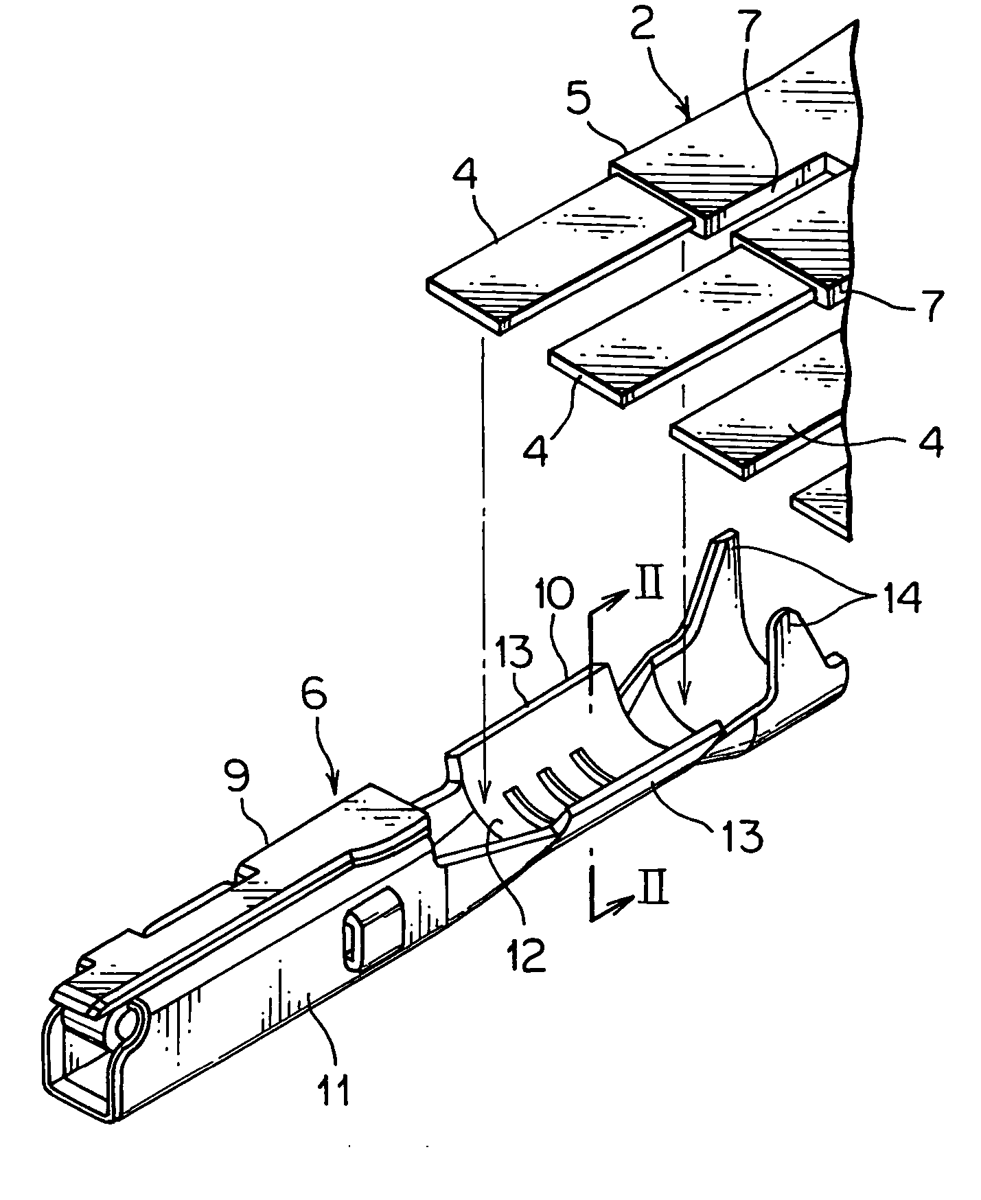
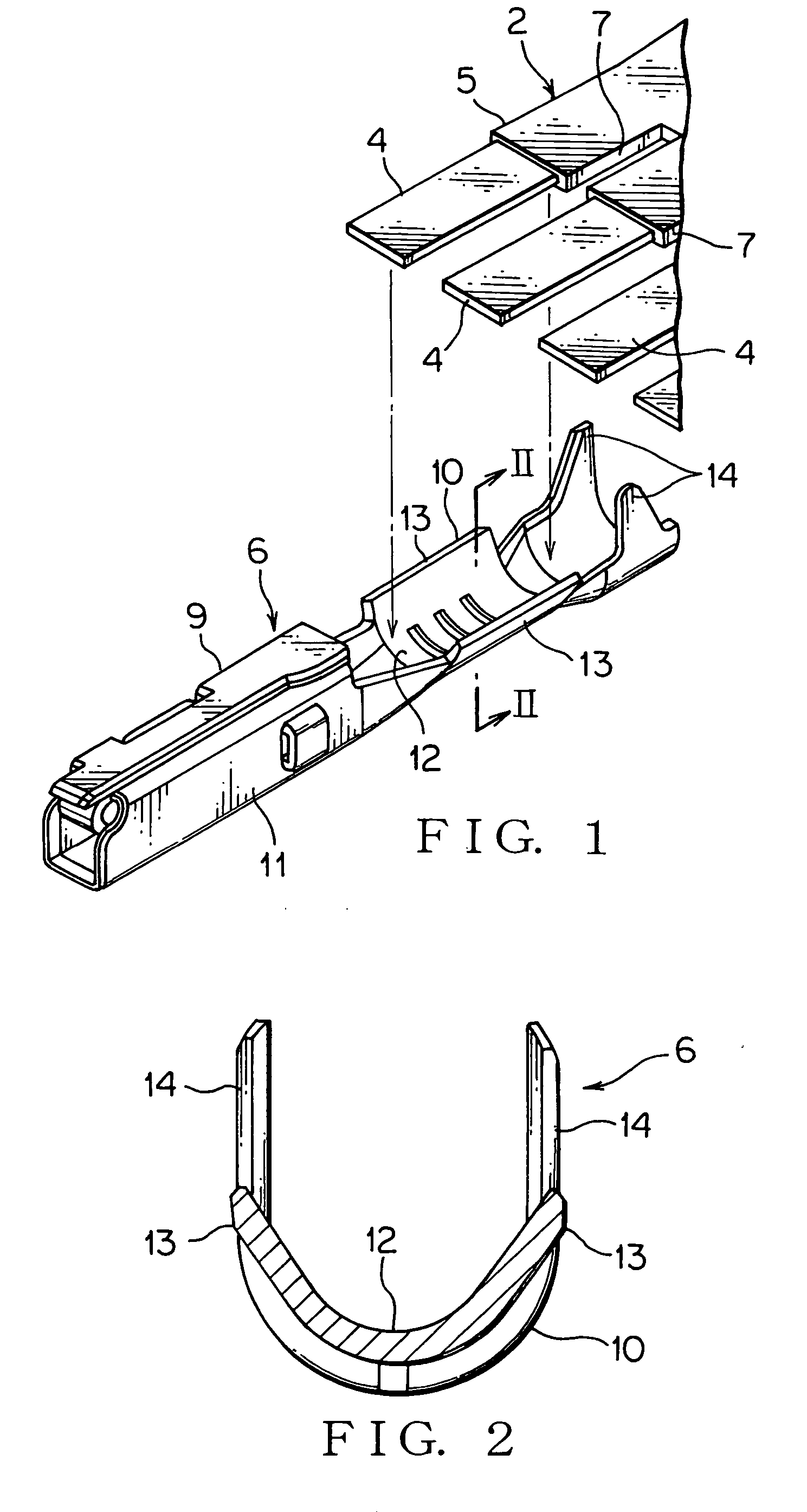
[0043] A crimping apparatus 1 shown in FIG. 5 serves to fit or crimp a conductor 4 of a FFC (Flexible Flat Cable) 2, which is a flat circuit shown in FIG. 1, to a terminal (terminal assembly) 6.

[0044] A FFC 2, as shown in FIG. 1, has a plurality of conductors 4 and sheathes 5 covering the conductors 4 to be defined in a flat band.

[0045] The conductor 4 is made of an electrically conductive metal. The conductor 4 includes copper or a copper alloy. The conductor 4 has a rectangular section and extends straight. A plurality of the conductors 4 are arranged to be parallel to each other.

[0046] The sheath 5 is made of an insulating synthetic resin and defined in a band. The sheath 5 is a flat band covering the conductor 4. The sheath 5 electrically insulates the conductors 4 from each other. The FFC 2 has a slit 7 between the conductors 4 and the shea...

second embodiment

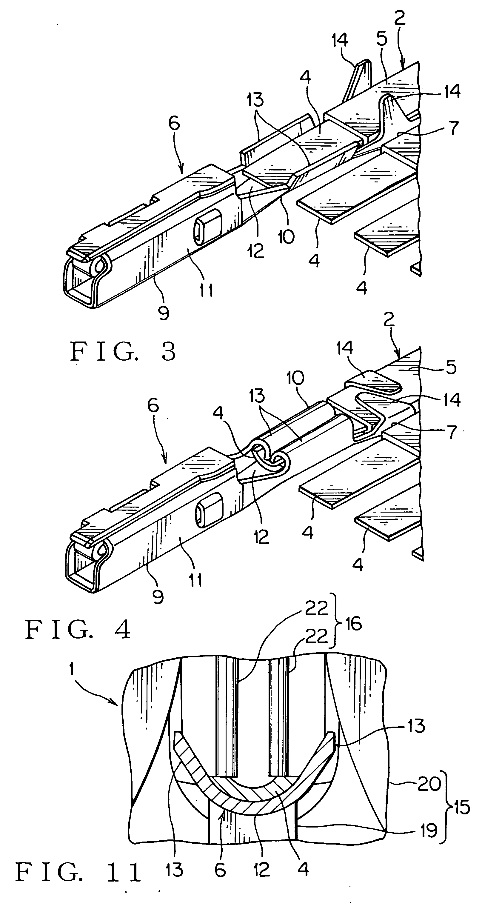
[0070] The crimping apparatus 1 of the second embodiment has a pressing portion 16 provided with a pair of stopping dies 27. The stopping dies 27 each are a flat plate having a comparatively large thickness and are spaced from and opposed to each other in a longitudinal direction of a terminal 6 arranged on the anvil 19. Between the stopping dies 27, a crimper 20 is disposed to be positioned therein. The stopping dies 27 contact the crimper 20 so as to slide along directions in which the crimper 20 comes close to and apart from the anvil 19. The pair of stopping dies 27 are in a row in a longitudinal direction of the terminal 6 set on the anvil 19. The stopping dies 27 are fitted to the rod 26 of the air cylinder 18, and the stopping dies 27 comes close to and apart from the anvil 19 according to extension and retraction of the rod 26.

[0071] The stopping die 27 has a main body 28 supported by the crimper 20 slidably along the extension and retraction direction of the crimper 20. The...


PUM

PropertyMeasurementUnit
electrical poweraaaaaaaaaa
weightaaaaaaaaaa
volumeaaaaaaaaaa

Abstract

The crimping apparatus crimps a conductor of a FFC (flexible flat cable) to a terminal. The crimping apparatus has a crimping portion and a pressing portion. The crimping portion has an anvil and a crimper which pinch the terminal and the conductor of FFC therebetween. The pressing portion has a pair of stopping bars. The stopping bars each are inserted into a through hole defined in the crimper. The stopping bars of the pressing portion press the conductor positioned on a bottom wall of the terminal against the bottom wall. The crimping portion crimps crimping pieces of the terminal with the stopping bars pressing the conductor against the bottom wall.

Description

BACKGROUND OF THE INVENTION [0001] 1. Field of the Invention [0002] The present invention relates to a crimping apparatus for fitting a terminal to a conductor of a flat circuit such as FPC (flexible printed circuit) and FFC (flexible flat cable). [0003] 2. Background Art [0004] An automotive vehicle has various types of electrical equipment. The automotive vehicle is arranged with wiring harnesses to supply electrical power from a battery and to transmit control signals from control units to the electrical equipment. The wiring harnesses have electrical cables, connectors, etc. The connector has a housing made of an insulating synthetic resin and a terminal received in the housing. The terminal is fitted to an end of one of the electrical cables. [0005] Recently, a user requests an automotive vehicle having multi-functions. Thus, the automotive vehicle tends to have an increase number of electronic instruments. This increases cables of the wiring harnesses so that the wiring harnes...

Claims


Application Information

Patent Timeline
Patent Type & Authority Applications(United States)
IPC IPC(8): H01R11/20
CPCH01R12/68H01R43/048H01R43/058Y10T29/5327Y10T29/53235Y10T29/49181Y10T29/49185
Inventor KUMAKURA, HIDETO
Owner YAZAKI CORP
Why Eureka
Try Eureka