
Time monitoring of packet retransmissions during soft handover

Active Publication Date: 2007-04-05
PANASONIC CORP
View PDF7 Cites 209 Cited by
  • Summary
  • Abstract
  • Description
  • Claims
  • Application Information

AI Technical Summary

Benefits of technology

[0075] The object of the present invention is to prevent erroneous combining of data packets in a packet retransmission scheme at the receiver. The erroneous combining may be caused by non-synchronized soft buffers of multiple receivers.
[0099] Another possibility to prevent the flushing of a buffer region associated to a specific data packet and its related retransmission data packets, may be to transmit a restart request message to a base station, wherein the restart request message indicates a data packet for which monitoring of the time elapsed since the storing of the data packet (or a related retransmission data packet) in the associated buffer region has to be restarted. A base station may receive this restart request message and restart the monitoring. The restart request message may comprise control information and no or dummy payload data. In another alternative embodiment of the present invention, upon expiry of the threshold time period, a base station may mark an associated buffer region of the packets as a buffer region to be flushed. If a new packet associated to that buffer region (e.g. identfied by the sequence number) is received it may finally flush the soft buffer unless it received some additional control information. Such control information may be a combine indicator. A combine indicator may be realized as flag which may be sent if the transmitted data packet should be combined. In the latter case the marked buffer region may not be flushed and a combining will still take place although the timer already expired. This may allow for a soft combing even if a retransmission of a data packet is delayed.

Problems solved by technology

The erroneous combining may be caused by non-synchronized soft buffers of multiple receivers.

Method used


Image

  • Time monitoring of packet retransmissions during soft handover
  • Time monitoring of packet retransmissions during soft handover
  • Time monitoring of packet retransmissions during soft handover

Examples


Embodiment Construction

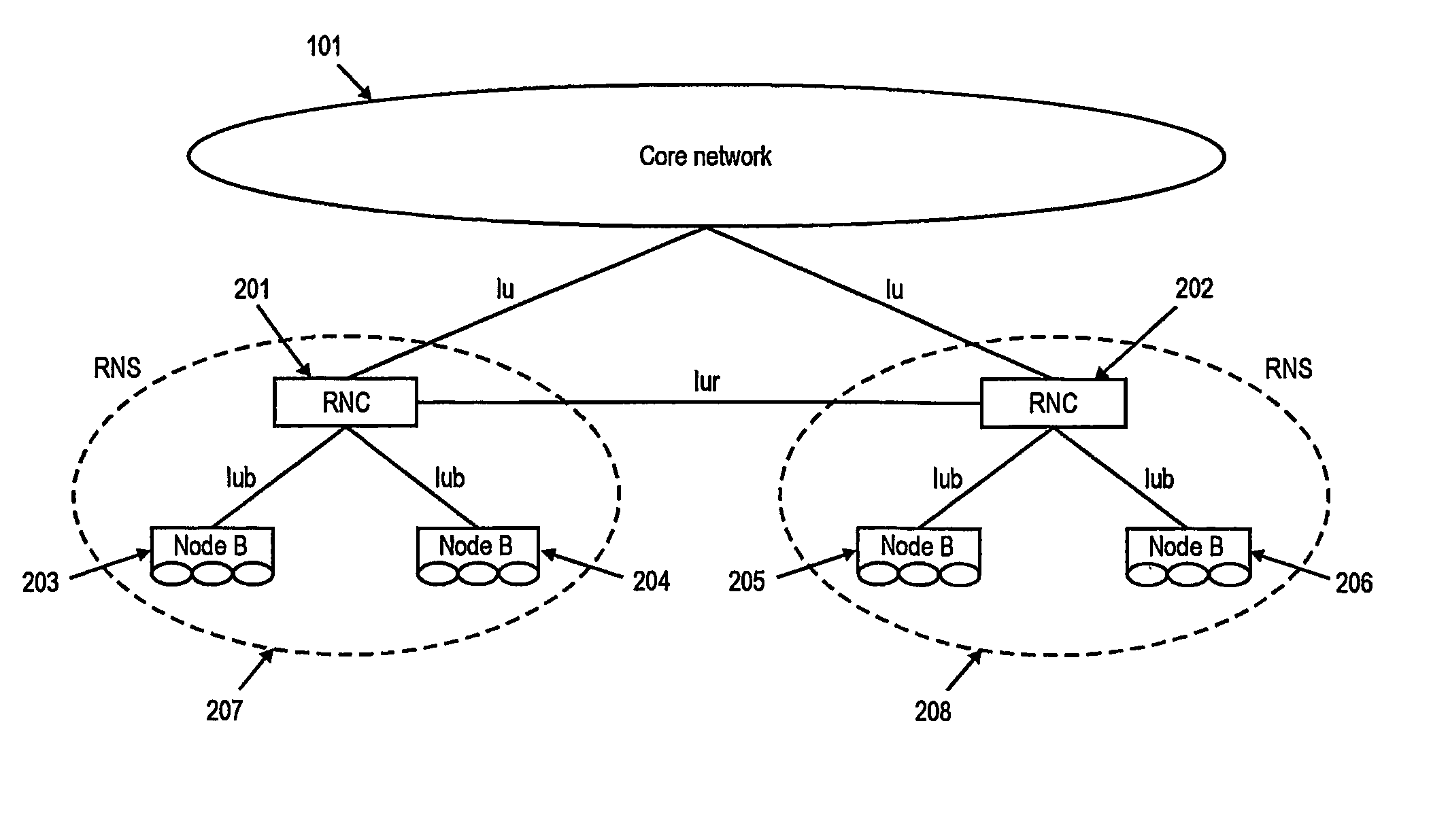
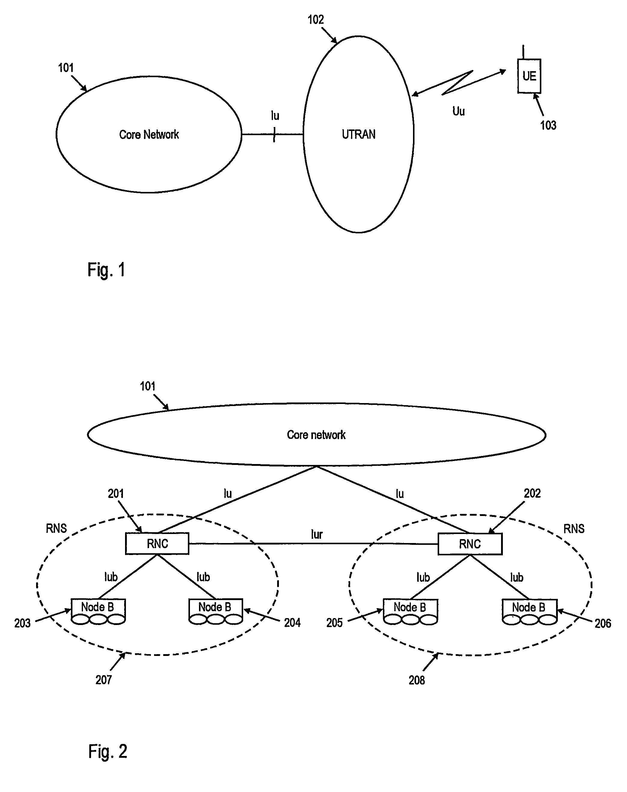
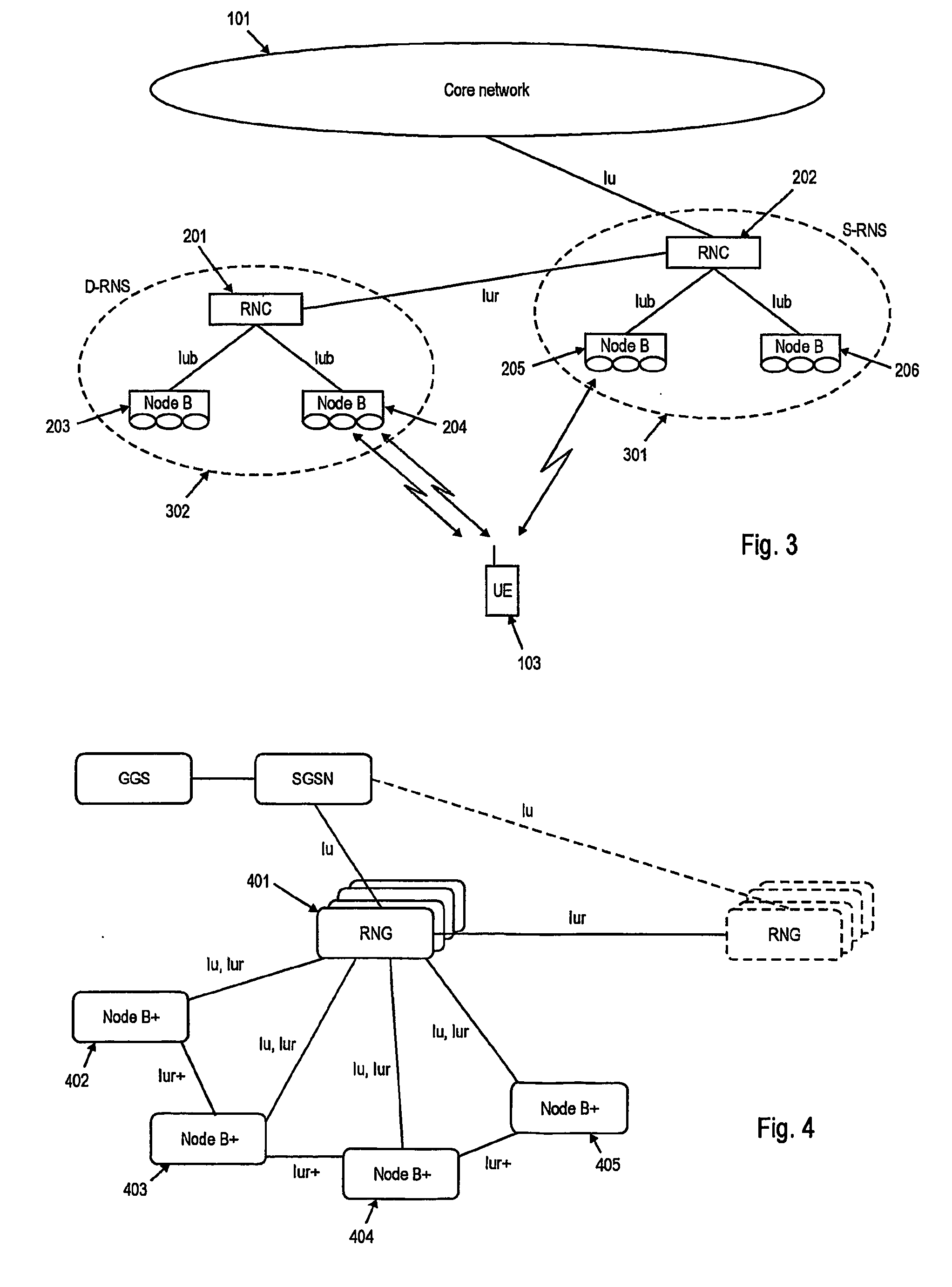
[0126] It is noted that the different embodiments in the following will be described mainly in 25 relation to the HARQ packet retransmission scheme and UMTS. Nevertheless, the principles underlying the present invention are also applicable to other data packet retransmission schemes and to other mobile communication systems than UMTS that provide soft handover of communication terminals and packet retransmission mechanisms.

[0127] In FIG. 11 shows an illustrative flow chart of the operation of a base station within the active set of a UE during soft handover. The base station may monitor the physical channels in step 1101 and may regularly check whether one or more data packets are received within a transmission time interval (TTI) in step 1102. If a data packet is sent to the base station, it is received in step 1103 and upon reception the base station decides, whether the received data packet is an initial data packet or a retransmission relating to an initial data packet in step ...


PUM


Abstract

The present invention relates to a method for scheduling data retransmissions, a method for use in a data retransmission scheme and a method for updating a soft buffer of a base station in a mobile communication system during a soft-handover. The present invention relates to a base station executing the controlling and updating method, a communication terminal for executing the scheduling method and to a mobile communication system comprising at least one the base station and communication terminal. To prevent erroneous combining of data packets in a packet retransmission scheme at the receiver, the present invention provides a method that may flush the soft bufferregion associated to areceived data packet upon its correct reception. Further, a method is provided that monitors the time elapsed since the last storing of a data packet in a buffer region of a base station to be able to trigger the flush of the buffer region upon expiry of a threshold time period.

Description

[0001] The present invention relates to a method for scheduling data retransmissions and a method for use in a packet retransmission scheme in a communication terminal being part of a mobile communication system comprising said communication terminal and a plurality of base stations, wherein said communication terminal is in communication with said plurality of base stations during a soft handover. Moreover the present invention relates to a method for updating a soft buffer of a base station being part of the mobile communication terminal. Further the present invention relates to a base station executing the method for controlling data retransmissions and a communication terminal executing the method for scheduling data retransmissions. Finally, the present invention relates to a mobile communication system comprising at least one the base station and at least one communication terminal. TECHNICAL BACKGROUND [0002] W-CDMA (wideband Code Division Multiple Access) is a radio interfac...

Claims


Application Information

Patent Timeline
IPC IPC(8): H04L1/18G08C25/02H04L1/16H04L12/26H04L12/56H04W28/04H04W28/14H04W36/02H04W36/08H04W36/18
CPCH04L1/16H04L1/1812H04L1/1845H04L1/1848H04L1/1887H04L12/2602H04L43/00H04W28/04H04W28/14H04W36/02H04W36/18H04L1/18
Inventor SEIDEL, EIKOLOHR, JOACHIMPETROVIC, DRAGAN
Owner PANASONIC CORP
Learn More