Trigger mechanism and a firearm containing the same

a technology of trigger mechanism and firearm, which is applied in the direction of firing/trigger mechanism, weapon components, weapons, etc., can solve the problems of affecting the safety of the firearm, the surface and edge edges of the two hardened steel components of the sear can degrade, and the sudden and unexpected discharge of the firearm without warning. , to achieve the effect of reducing friction and crisp feel during discharg

Inactive Publication Date: 2007-04-12
KARAGIAS THEODORE
View PDF95 Cites 29 Cited by
  • Summary
  • Abstract
  • Description
  • Claims
  • Application Information

AI Technical Summary

Benefits of technology

[0017] The trigger mechanism and/or the firearm in accordance with the present invention may also have a ratio of sear engagement to trigger pull distance greater than or equal to 0.5 and less than or equal to 10.0. Moreover, the trigger mechanism and/or the fir

Problems solved by technology

Obtaining a lightweight trigger while maintaining safety has been difficult.
However, certain problems exist with such an approach.
The surfaces and edges of the two hardened steel components of the sear can degrade over time by wear, corrosion, and additional factors.
Therefore, accidental discharge of the firearm can suddenly occur without warning after prolonged use or storage, especially in a corrosive environment.
Even the presence of a safety mechanism may not be satisfactory.
For example, if a saf

Method used


Image

  • Trigger mechanism and a firearm containing the same
  • Trigger mechanism and a firearm containing the same
  • Trigger mechanism and a firearm containing the same

Examples


Embodiment Construction

[0060] The present invention will now be described more fully hereinafter, in which various embodiments of the invention are shown. This invention may, however, be embodied in many different forms and should not be construed as being limited to the embodiment explicitly set forth herein.

1. Firearm

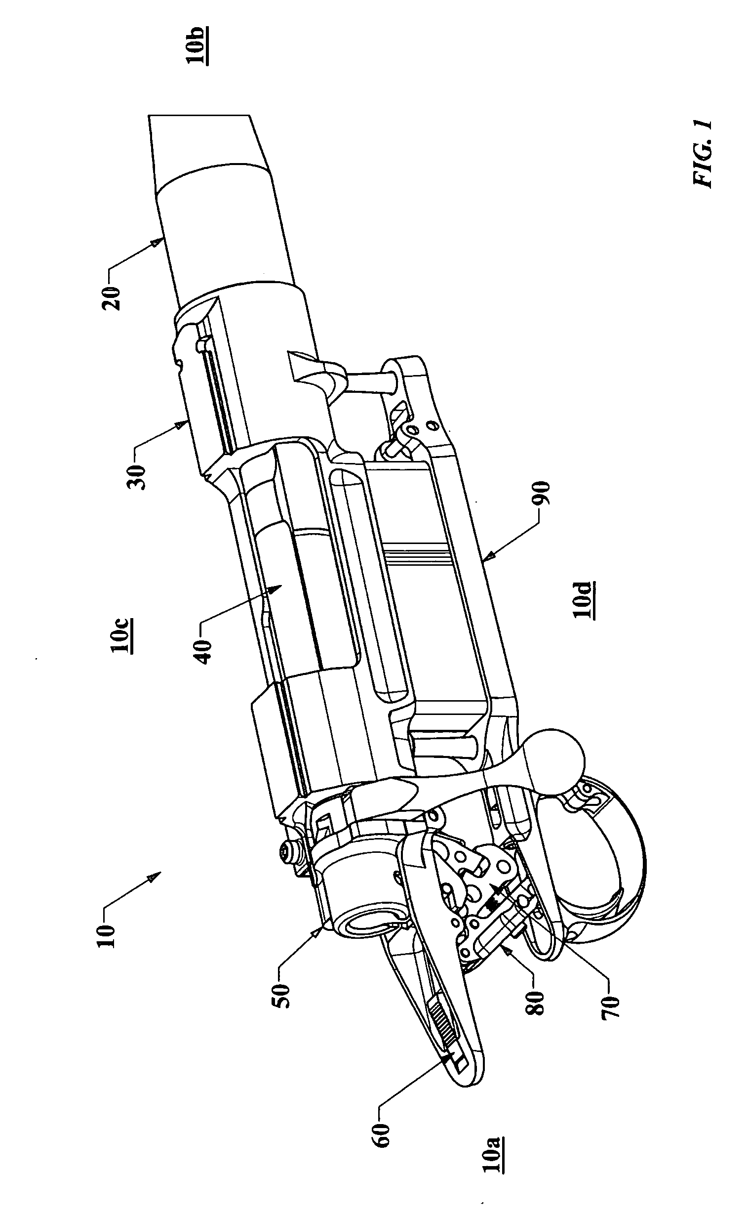
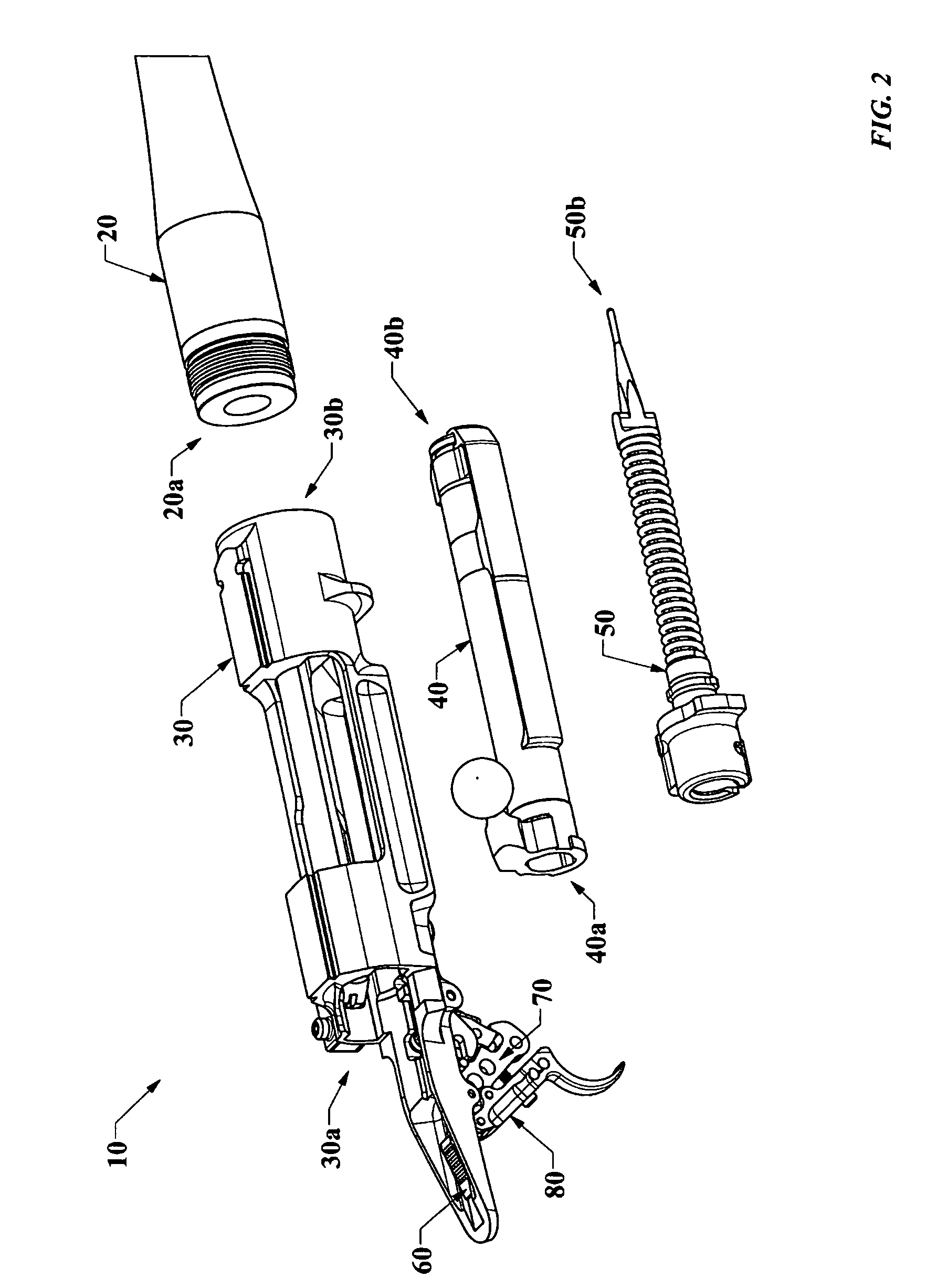
[0061] In accordance with certain embodiments of the present invention, FIG. 1 shows a view of a firearm 10 composed of a barrel 20, a receiver assembly 30, a bolt assembly 40, a firing pin assembly 50, a safety assembly 60, a sear assembly 70, a trigger assembly 80, and a floor plate assembly 90. Barrel 20 is connected to receiver assembly 30. Receiver assembly 30 is connected to bolt assembly 40, firing pin assembly 50, safety assembly 60, sear assembly 70, trigger assembly 80, and floor plate assembly 90. Trigger assembly 80 is connected to sear assembly 70.

[0062] As indicated in FIG. 1, a proximal end 10a of firearm 10 refers a region near trigger assembly 80, and the distal end 10b...


PUM


Abstract

A firearm and a trigger mechanism having a small trigger pull force, small trigger pull distance, and a large sear engagement is provided. The firearm and trigger mechanism of the present invention provides a safe firearm having a light and crisp trigger pull. Certain embodiments of the present invention may also provide for a firearm or trigger mechanism having a ratio of sear engagement to trigger pull distance that is greater than or equal to 1.0. Certain embodiments of the present invention may also provide for a firearm and a trigger mechanism operably connected with one or more jewel bearings.

Description


Claims


Application Information

Patent Timeline
Owner KARAGIAS THEODORE
Why Eureka
Try Eureka