Multi-cyclone dust collector for vacuum cleaner

a vacuum cleaner and dust collector technology, applied in the field of vacuum cleaners, can solve the problems of decreased efficiency of contaminants collecting, and low efficiency of contaminants collecting from conventional cyclone dust collectors, and achieve the effect of high contaminants collecting efficiency

Inactive Publication Date: 2007-04-12
SAMSUNG GWANGJU ELECTRONICS CO LTD
View PDF1 Cites 43 Cited by
  • Summary
  • Abstract
  • Description
  • Claims
  • Application Information

AI Technical Summary

Benefits of technology

[0011] The present invention has been developed in order to overcome the above drawbacks and other problems associated with the conventional art. An aspect of the present invention is to provide a multi-cyclone dust collector that can separate fine contaminants and has a high contaminants collecting efficiency.
[0012] Another aspect of the present invention is to provide a multi-cyclone dust collector that can discharge contaminants through an upper side thereof for the convenience of emptying contaminants.
[0013] Still another aspect of the present invention is to provide a compact multi-cyclone dust collector having a shorter height than the conventional multi-cyclone dust collector.

Problems solved by technology

Therefore, the conventional cyclone dust collector has a low contaminants collecting efficiency due to collision between the rising air and the descending air.
Furthermore, the conventional cyclone dust collectors cannot separate fine contaminants.
However, the conventional multi-cyclone dust collector still has a problem: contaminants collecting efficiency is decreased due to collision between the rising air and the descending air.
Also, the conventional multi-cyclone dust collector has a large size, especially a large height because the number of cyclones is increased.

Method used


Image

  • Multi-cyclone dust collector for vacuum cleaner
  • Multi-cyclone dust collector for vacuum cleaner
  • Multi-cyclone dust collector for vacuum cleaner

Examples


Embodiment Construction

[0043] Hereinafter, certain exemplary embodiments of the present invention will be described in detail with reference to the accompanying drawings.

[0044] The matters defined in the description, such as a detailed construction and elements thereof, are provided to assist in a comprehensive understanding of the invention. Thus, it is apparent that the present invention may be carried out without those defined matters. Also, well-known functions or constructions are omitted to provide a clear and concise description of exemplary embodiments of the present invention.

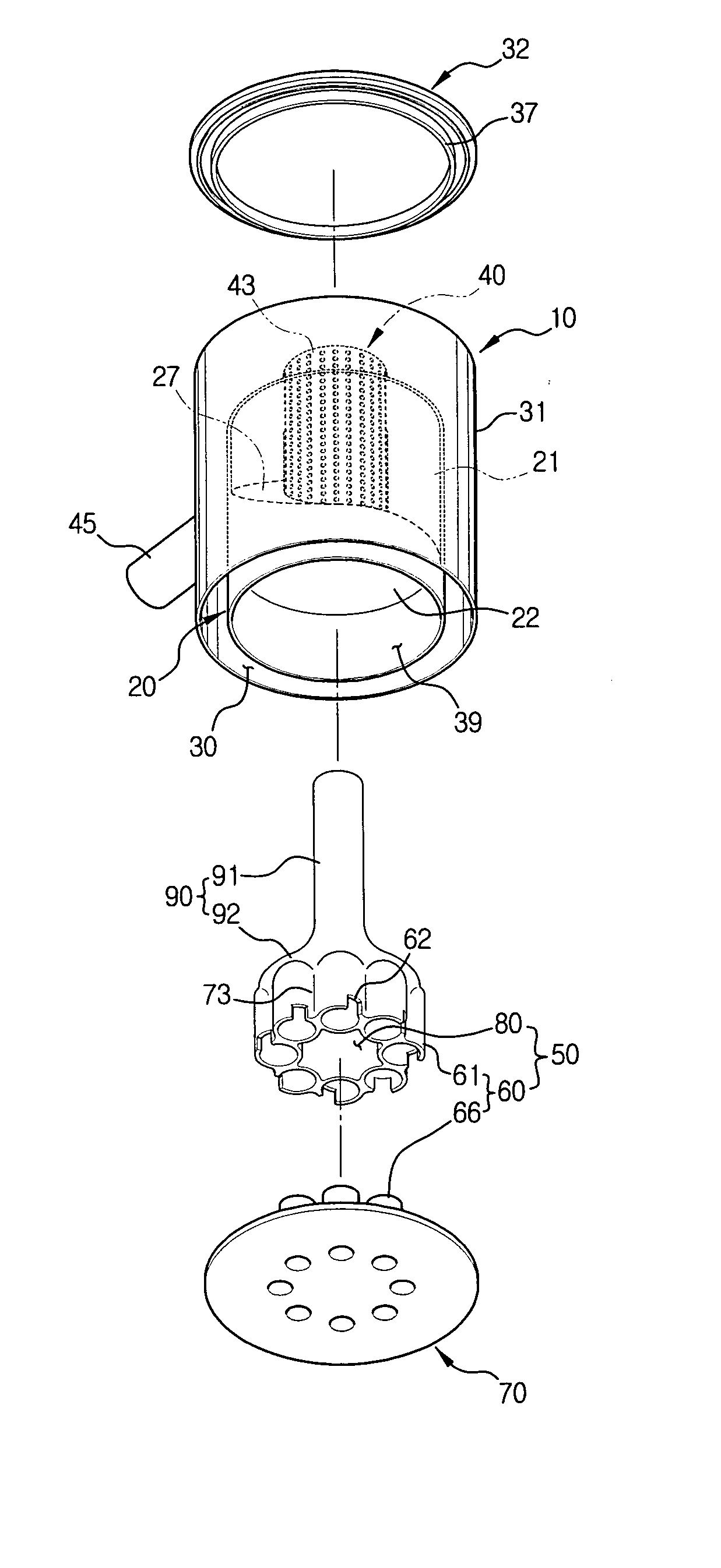
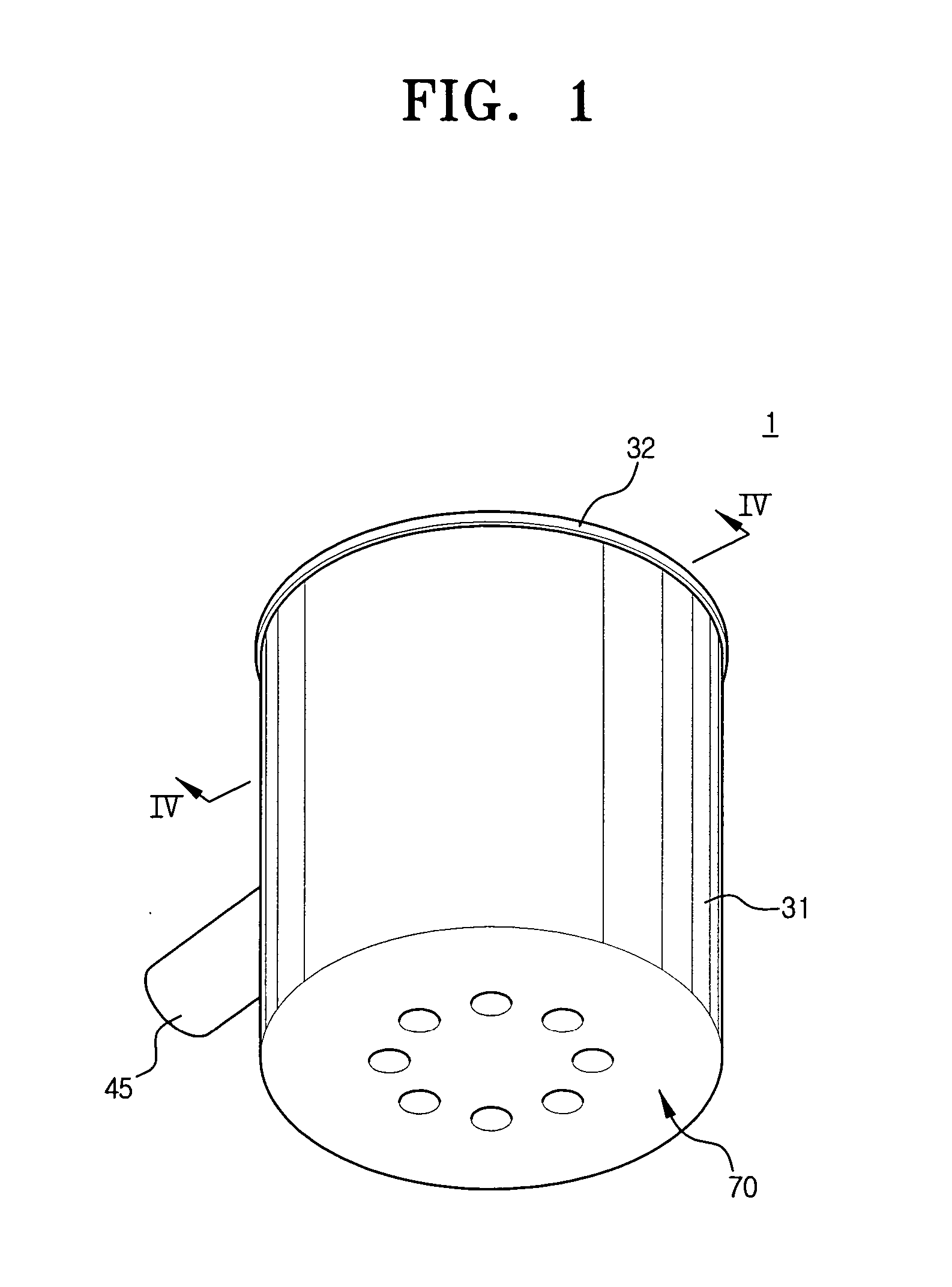
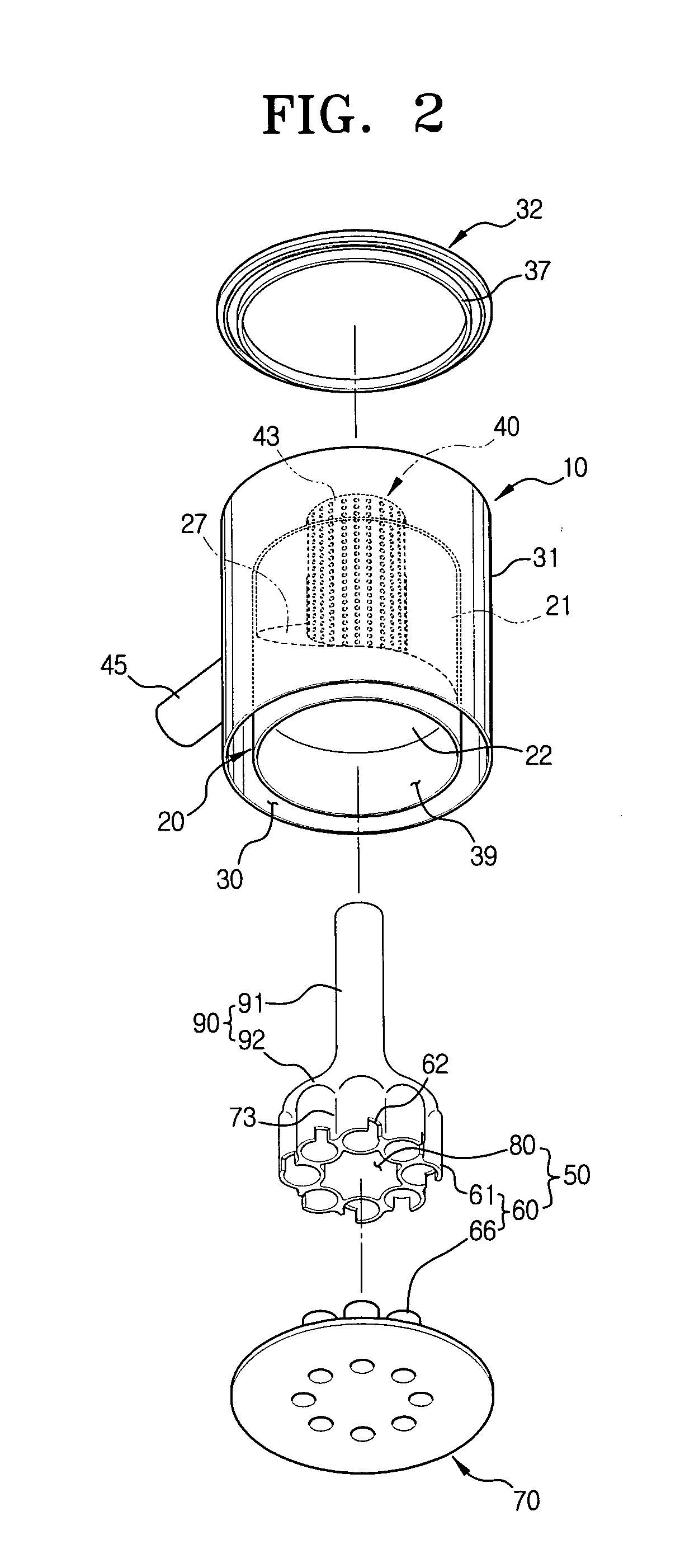
[0045] Referring to FIGS. 1 to 4, a multi-cyclone dust collector 1 for a vacuum cleaner according to an embodiment of the present invention includes a first cyclone unit 10, a second cyclone unit 50, and a contaminants discharging member 90.

[0046] The first cyclone unit 10 takes outside air, which contains contaminants such as dust, dirt and so on and is sucked into a suction brush 110 (see FIG. 7) (hereinafter, referred ...


PUM

PropertyMeasurementUnit
cylindrical shapeaaaaaaaaaa
shapeaaaaaaaaaa
circular shapeaaaaaaaaaa

Abstract

A multi-cyclone dust collector for a vacuum cleaner includes a first cyclone unit forcing contaminants-laden air to form an upwardly whirling air current so as to centrifugally separate contaminants from the contaminants-laden air, the first cyclone unit having an air communicating member; a second cyclone unit being disposed under the first cyclone unit, the second cyclone unit forcing partially cleaned air discharged through the air communicating member to be sucked into a lower portion of the second cyclone unit and to form a second upwardly whirling air current so as to centrifugally separate fine contaminants from the partially cleaned air, the second cyclone unit having a plurality of second cyclones; and a contaminants discharging member being disposed over the second cyclone unit inside the air communicating member for discharging the fine contaminants separated in the second cyclone unit to an upper side of the air communicating member.

Description

CROSS-REFERENCE TO RELATED APPLICATIONS [0001] This application claims the benefit under 35 U.S.C. § 119(a) from Korean Patent Applications No. 2005-95417, filed Oct. 11, 2005 and No. 2005-98773, filed Oct. 19, 2005 in the Korean Intellectual Property Office, the disclosure of both of which are incorporated herein by reference in its entirety. BACKGROUND OF THE INVENTION [0002] 1. Field of the Invention [0003] The present invention relates to a vacuum cleaner. More particularly, the present invention relates to a multi-cyclone dust collector for a vacuum cleaner for separating contaminants from sucked air. [0004] 2. Description of the Related Art [0005] Generally, a vacuum cleaner generates a suction force by a vacuum generator including an impeller and a motor. Contaminants such as dust or dirt on a cleaning surface are sucked into the vacuum cleaner with outside air by the suction force. When sucked contaminants and outside air pass through a dust collecting apparatus that is disp...

Claims


Application Information

Patent Timeline
Patent Type & Authority Applications(United States)
IPC IPC(8): B01D45/12
CPCA47L9/1608A47L9/1625A47L9/1641A47L9/1683B04C5/13B04C5/185B04C5/26
Inventor KIM, TAK-SOO
Owner SAMSUNG GWANGJU ELECTRONICS CO LTD
Why Eureka
Try Eureka