Device and process for luminescence imaging

Inactive Publication Date: 2007-04-12
BIOSPACE LAB
View PDF14 Cites 26 Cited by
  • Summary
  • Abstract
  • Description
  • Claims
  • Application Information

AI Technical Summary

Benefits of technology

[0033] (a) having an electronic control unit define a plurality of time frames, and having said control unit cause the light source to generate incident

Problems solved by technology

However, that apparatus does not make it possible to monitor rapid variation over time of the information relating to the luminescence.
If the sample moves while the measurement is taking place (in particular if it is necessary for the sample to move while the measurement is taking place because the measurement corresponds to muscular activity that cannot be recorded for a anesthetized sample), such an installation is not suitable.

Method used


Image

  • Device and process for luminescence imaging
  • Device and process for luminescence imaging
  • Device and process for luminescence imaging

Examples


first embodiment

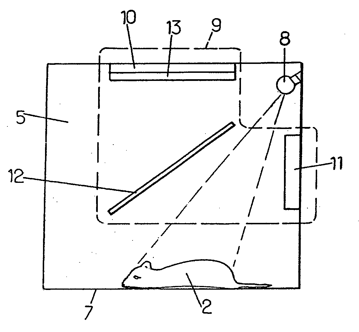
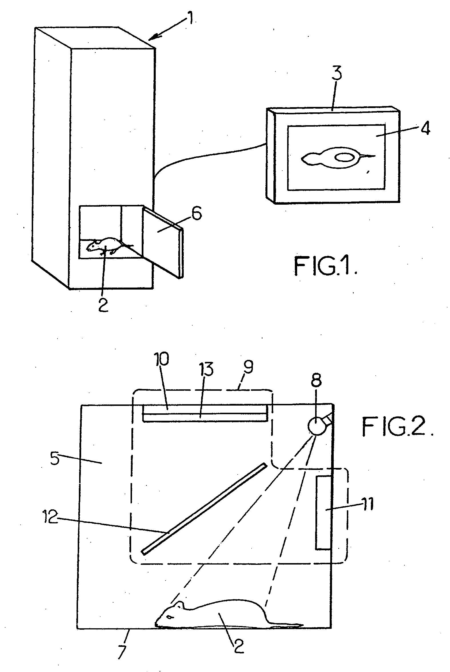
[0093] In the first embodiment shown with reference to FIG. 2, the detection apparatus comprises a first detector 10 suitable for detecting light signals coming from the sample 2 that present a luminescence spectrum. Such a first detector 10 is, for example, a cooled charge-coupled device (CCD) camera presenting a matrix of pixels disposed in rows and in columns, an intensified CCD (ICCD), an electron multiplying CCD (EMCCD, i.e. a CCD with internal multiplication) or the like. The detection apparatus 9 further comprises a second detector 11 which, for example, is a conventional or an intensified CCD camera, presenting a large number of pixels disposed in rows and in columns. In the example shown in FIG. 2, each of the first and second detectors 10, 11 is disposed on a distinct face of the enclosure 5.

[0094] In the example shown, the light source 8 emits incident illumination continuously towards the stage so that the combined light signal corresponds to a spectral combination of th...

third embodiment

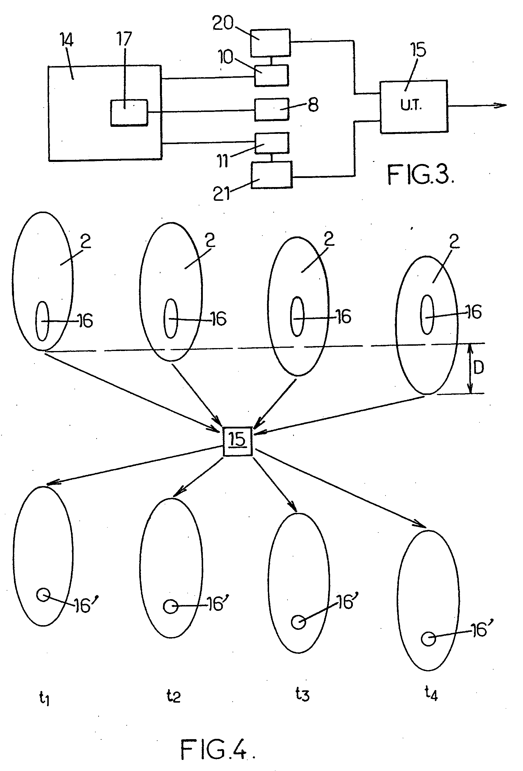
[0112] However, in the method described herein, the signal making it possible to obtain information on the position of the sample in the enclosure is not necessarily an optical signal. In the invention, shown in FIG. 7, any type of detector making it possible to obtain information on the position of the sample 2 in the enclosure is used for the first detector 10. Such a detector can, for example, be constituted by a thermal detector adapted to detect heat given off from the mammal 2. Therefore, in such an embodiment, it is no longer necessary to illuminate the sample 2 by means of a light source 8. In addition, the luminescence signal detected by the second detector 11, and the heat signal detected by the first detector 10 are so different that the separation of the signals takes place naturally by using detectors of different types. The thermal detector is not disturbed by the luminescence signal emitted by the sample and the detector of the luminescence signal is not disturbed by ...


PUM


Abstract

The luminescence imaging apparatus comprises: a stage receiving a sample (2) emitting luminescence information about the sample; a light source (8) illuminating the stage; and an electronic control unit defining time frames; a combined light signal corresponding to a combination of luminescence information and of the reflection on the sample of the illumination. During each time frame, the detection apparatus (9) acquires both first data relating to the luminescence information, and also second data relating to the second light signal.

Description

TECHNICAL FIELD [0001] The present invention relates to methods and apparatus for luminescence imaging. BACKGROUND OF THE INVENTION [0002] More particularly, the invention relates mainly to luminescence imaging apparatus comprising: [0003] a light-tight enclosure containing a stage adapted to receive a sample that is to be imaged and that emits a first light signal carrying luminescence information about the sample; [0004] a light source adapted to generate incident illumination towards the stage, the interaction between said incident illumination and the sample forming a second light signal; [0005] detection apparatus adapted firstly to detect light signals presenting a luminescence spectrum and to store a first image on the basis of the light signals presenting a luminescence spectrum, and secondly to detect light signals corresponding to the reflection on the sample of the incident illumination coming from said light source and to store a second image on the basis of the light si...

Claims


Application Information

Patent Timeline
IPC IPC(8): G01J1/58A61B6/00F21V9/16G01T1/10G21H3/02G21K5/00
CPCA61B5/0059A61B5/0064G01N21/6456G01N21/763G01N2021/6421A61B2503/40
Inventor MAITREJEAN, SERGEASSELIN, PASCALRONCALI, EMILIETAVITIAN, BERTRAND
Owner BIOSPACE LAB
Why Eureka
Try Eureka