Auto document feeder

Inactive Publication Date: 2007-04-12
ASIA OPTICAL INT LTD
View PDF5 Cites 19 Cited by
  • Summary
  • Abstract
  • Description
  • Claims
  • Application Information

AI Technical Summary

Benefits of technology

[0009] As such, the switching gate is internal to the ejecting roller unit, th

Problems solved by technology

As such, the structure of the auto document feeder is complicated, t

Method used


Image

  • Auto document feeder
  • Auto document feeder
  • Auto document feeder

Examples


Example

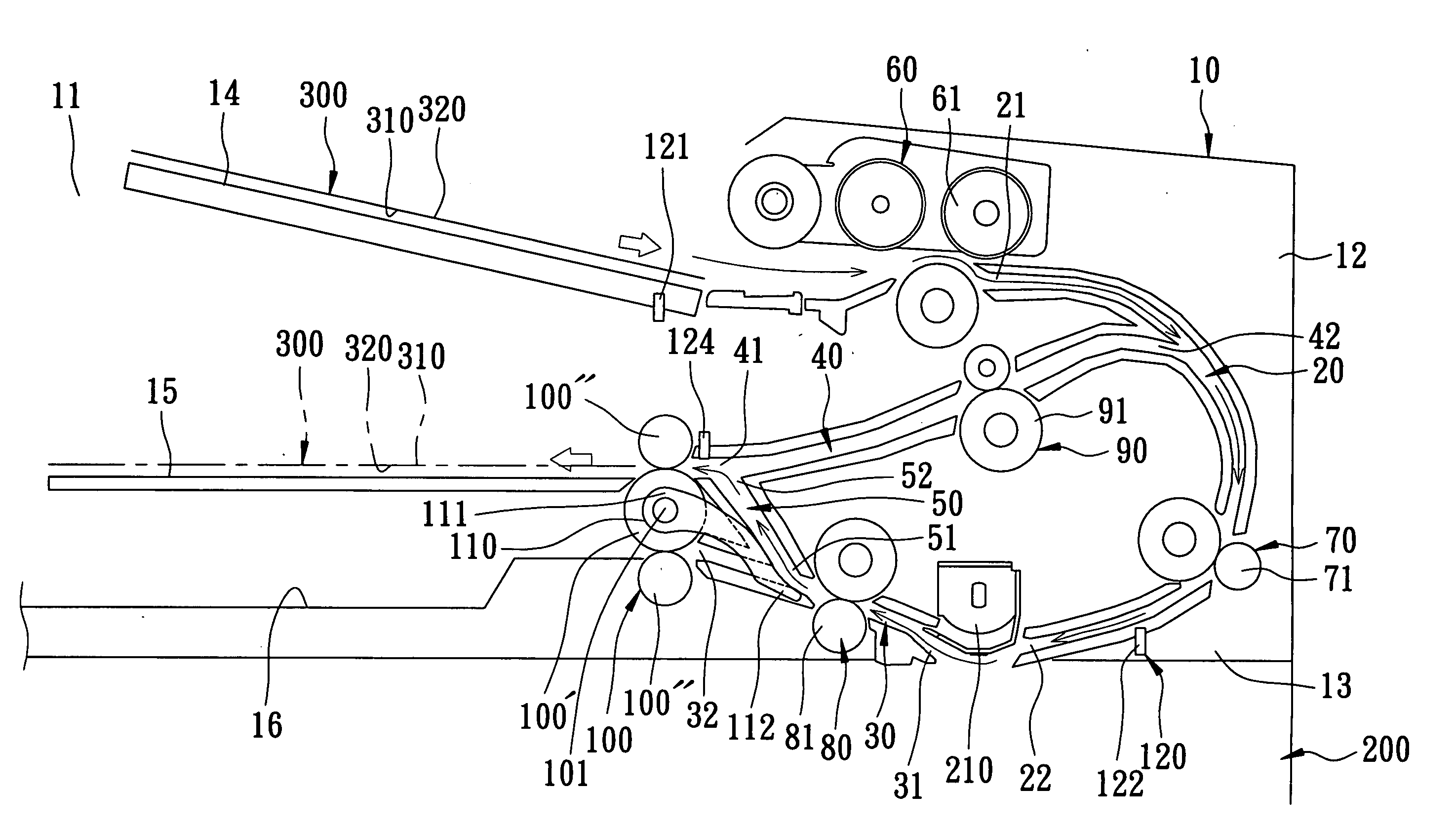
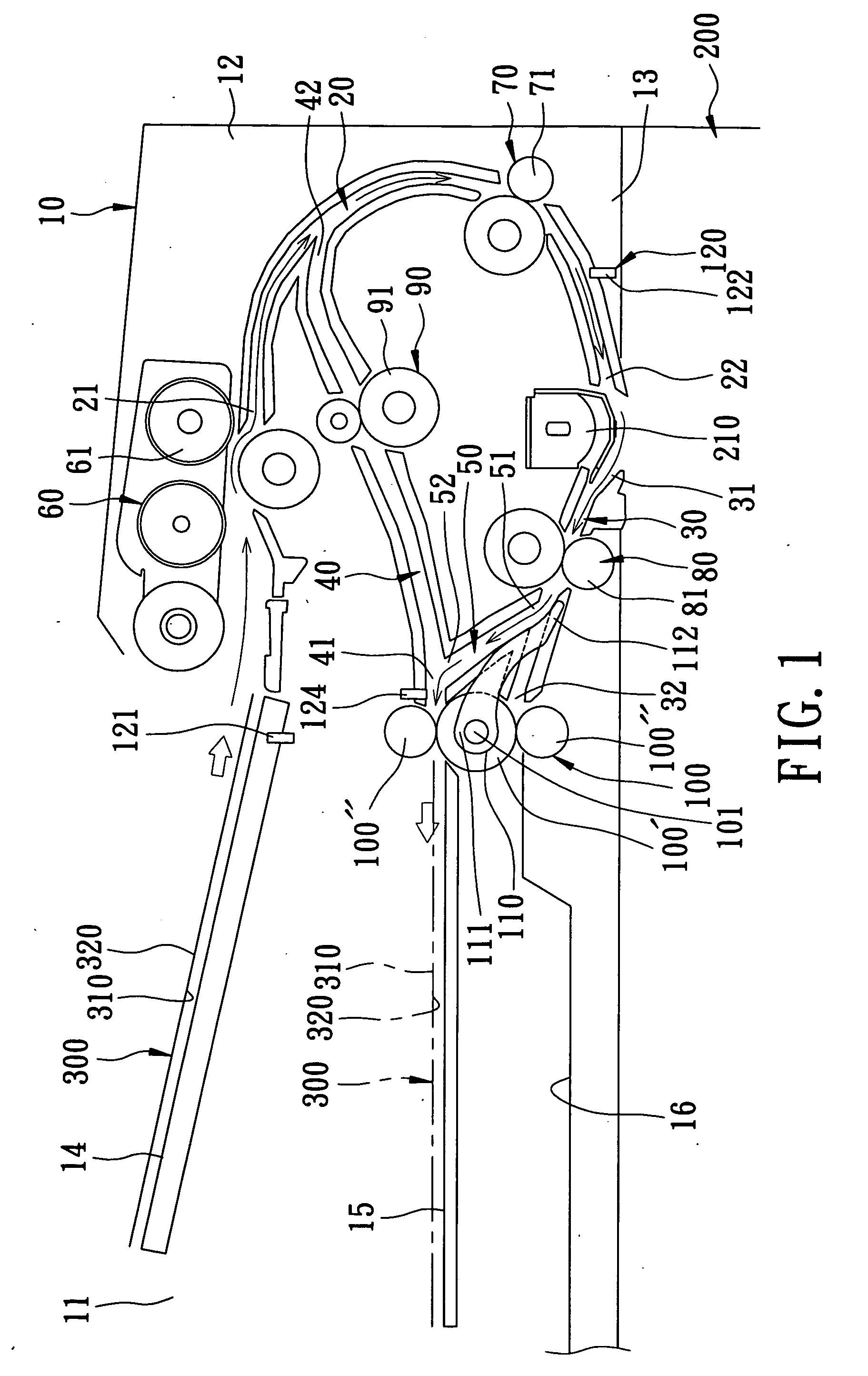
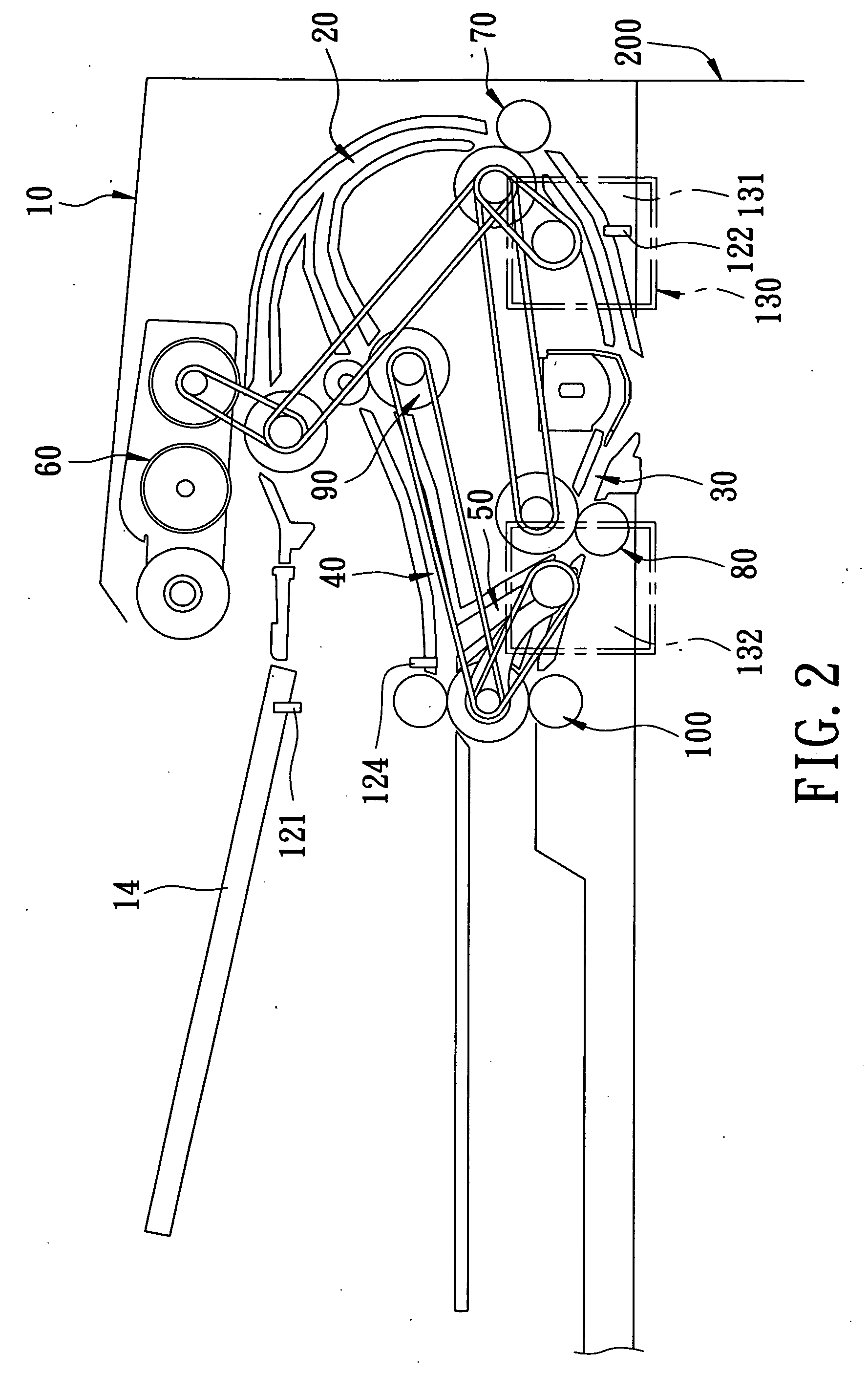
[0016] Referring to FIGS. 1 and 2, the preferred embodiment of an auto document feeder according to this invention is disposed on an image forming apparatus 200 (such as a copier) for feeding duplex documents 300. Each of the duplex documents 300 has opposite first and second side surfaces 310, 320. The image forming apparatus 200 includes a scanning unit 210. The auto document feeder includes a housing unit 10, a first path 20 disposed in the housing unit 10, a second path 30 in spatial communication with the first path 20, an inverting path 40 disposed above the second path 30, an inclined bypass path 50 interconnecting the second path 30 and the inverting path 40, a feeding roller unit 60 aligned with the first path 20, a first transfer roller unit 70 disposed on the first path 20, a second transfer roller unit 80 disposed on the second path 30, a third transfer roller unit 90 disposed on the inverting path 40, an ejecting roller unit 100, a switching gate 110 disposed on an inne...


PUM

PropertyMeasurementUnit
Proximity effectaaaaaaaaaa

Abstract

An auto document feeder includes a housing unit, spatially interconnected first and second paths, an inverting path in spatial communication with the first path, a bypass path spatially intercommunicating the second path and the inverting path, a feeding roller unit for feeding documents onto the first path, first and second transfer roller units disposed respectively on the first and second paths, an ejecting roller unit aligned with the second path and the inverting path, and a switching gate disposed between the ejecting roller unit and the second transfer roller unit and pivotable to extend onto the second path or the bypass path so as to guide movement of the documents.

Description

CROSS-REFERENCE TO RELATED APPLICATION [0001] This application claims priority of Taiwanese Application No. 094135165, filed on Oct. 7, 2005. BACKGROUND OF THE INVENTION [0002] 1. Field of the Invention [0003] This invention relates to an office machine, and more particularly to an auto document feeder for use in an office machine. [0004] 2. Description of the Related Art [0005] U.S. Pat. No. 5,784,680 discloses a compact auto-document feeder for an image forming apparatus that includes a switching gate, which is disposed pivotally downstream of a second feeding path and above an ejecting tray to lead selectively documents from the second feeding path to the ejecting tray, a switch-back path, or to an inverting path. [0006] Since the switching gate is external to an ejecting roller, a switch-back path and two switch-back rollers are required for facilitating ejecting of the documents. As such, the structure of the auto document feeder is complicated, thereby resulting in an increase...

Claims


Application Information

Patent Timeline
IPC IPC(8): B65H5/22B65H83/00B65H85/00
CPCH04N1/00572H04N1/00578H04N1/0058B65H2301/33312H04N1/00631H04N1/12B65H85/00H04N1/00602
Inventor TU, HAO
Owner ASIA OPTICAL INT LTD
Why Eureka
Try Eureka