
Object detection system and object detection method

a detection system and object technology, applied in the direction of detection using electromagnetic waves, pedestrian/occupant safety arrangements, instruments, etc., can solve the problems of deteriorating detection accuracy, interference with accurate collating operation, and deterioration of detection accuracy of the aforementioned object detection system

Active Publication Date: 2007-04-12
TOYOTA JIDOSHA KK
View PDF6 Cites 34 Cited by
  • Summary
  • Abstract
  • Description
  • Claims
  • Application Information

AI Technical Summary

Benefits of technology

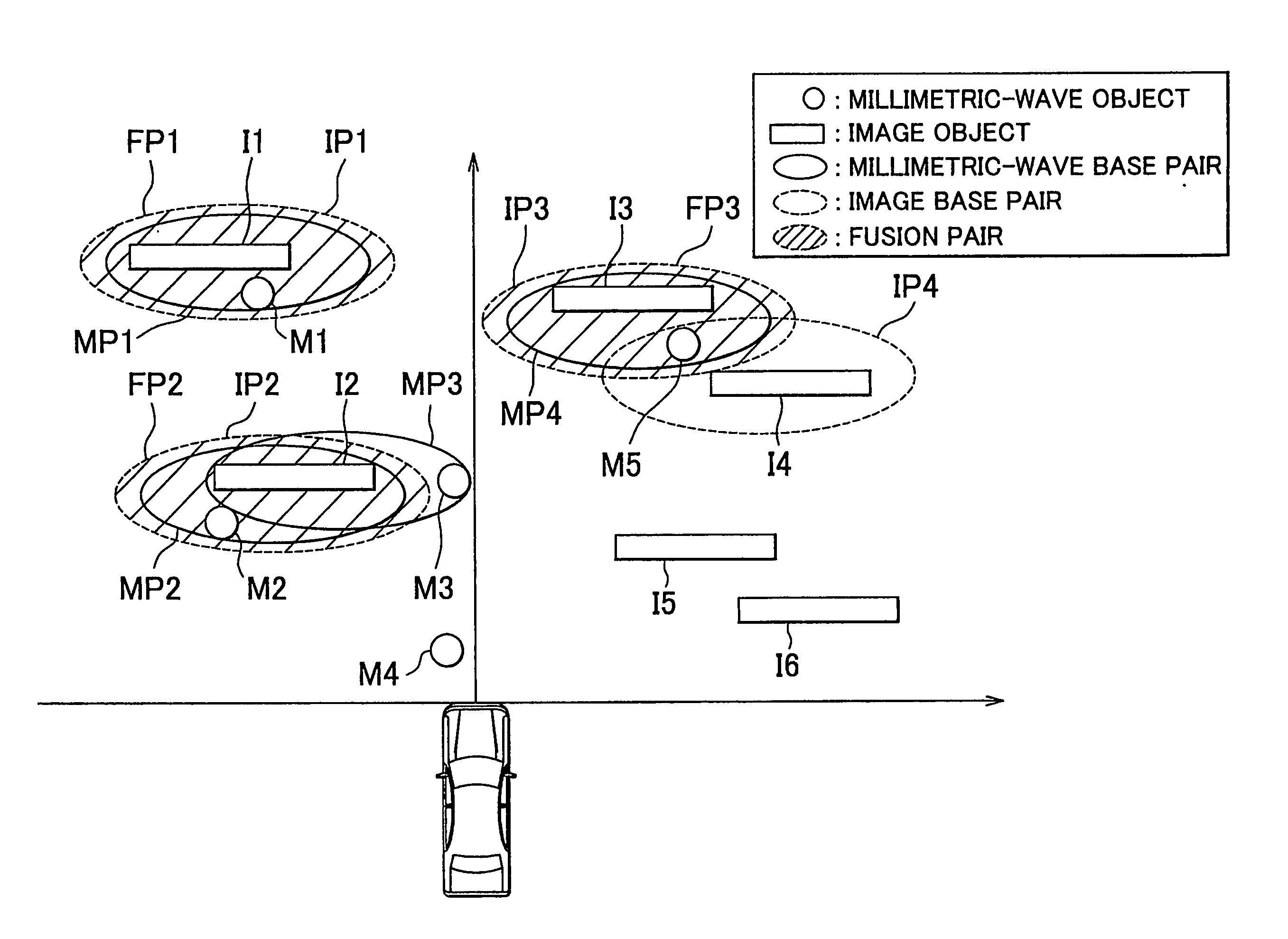
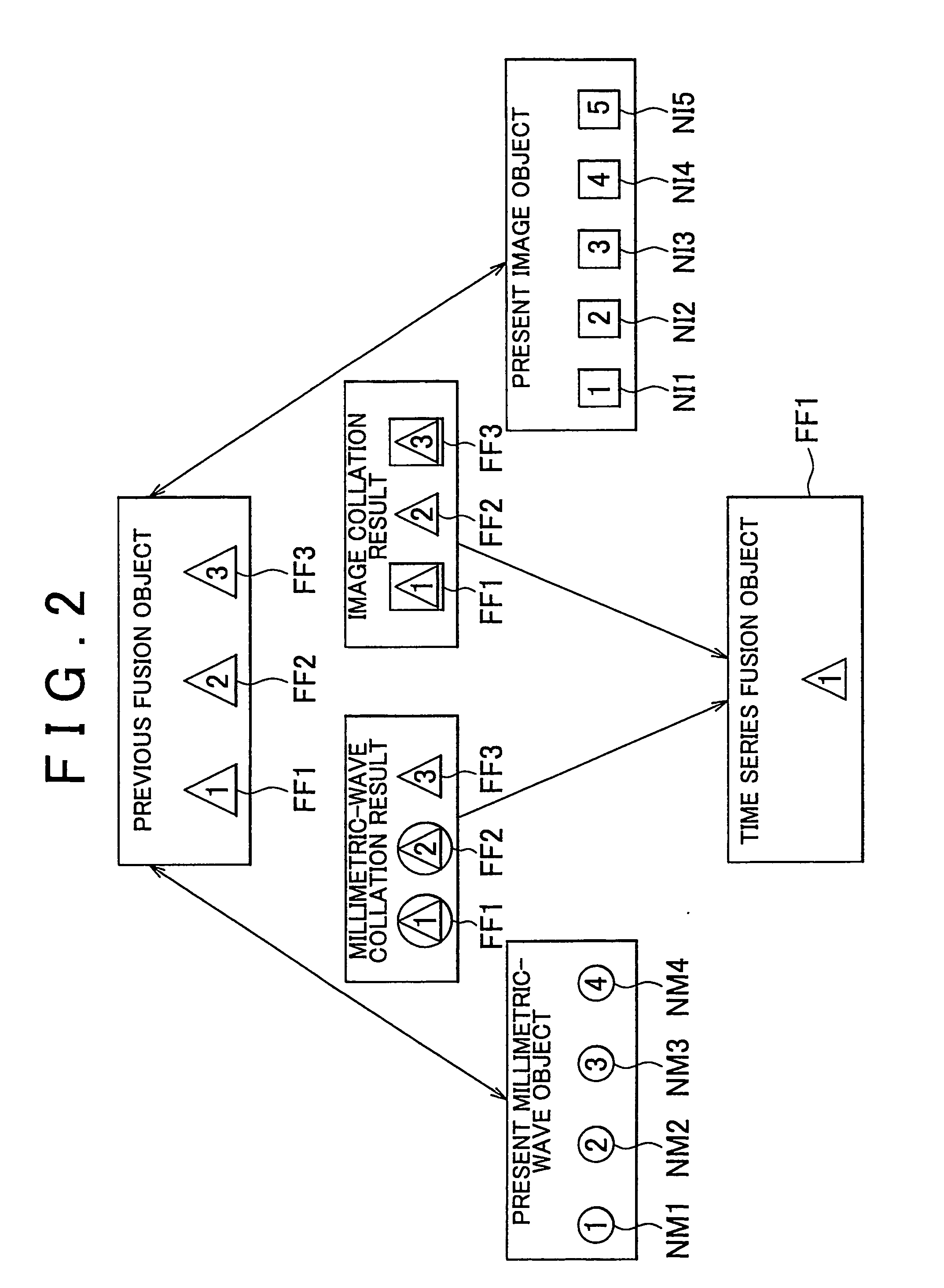
[0009] In the object detection system and object detection method, the object is detected by the radar detection means and the image detection means. The collating means of the object detection system and object detection method performs collation between detection results of the radar detection means and detection results of the image detection means at a predetermined time interval. If it is determined that the same object is detected by the aforementioned two detection units based on the results of the previous collation, the present collation is performed using the previous collation results. More specifically, the collating means performs collation between the object detected by the two detection units in the previous collation and the objects presently detected by the radar detection means, and between the object detected by the two detection units in the previous collation and the objects presently detected by the image detection means. Then it is determined whether the identical object is detected by those two detection units based on results of collation of the previous collation results with those of the object presently detected by the radar detection means and the image detection means. The detection results of the two detection units are not directly collated with each other, but each detection results of the two detection units is time-series collated using the previous collation results. This may improve the detection accuracy and stabilize the detection compared with the generally employed object detection system in which instantaneous detection results are collated. Even if the accuracy of at least one of those two detection units is deteriorated instantaneously, the collation may be performed using the previous collation results. Accordingly the detection results of the two detection units may be easily collated.
[0012] In the case where it is determined that the identical object is detected by the two detection units in the present collation using the previous collation results, the determined object is excluded from the objects presently detected by the radar detection means and the image detection means, respectively so as to be collated. It is determined whether there is the identical object among those presently detected by the two detection units. In the object detection system and object detection method, instantaneous collation is performed between the two detection units that have been instantaneously obtained by the two detection units in consideration with the time-series collation results. Accordingly the object detection system makes it possible to collate objects that have been presently detected reliably.

Problems solved by technology

Deterioration in accuracy of at least one of those detection units may interfere with accurate collating operation.
The detection accuracy of the aforementioned object detection system is likely to be deteriorated even if two different detection units are employed.
Accordingly, such system may mistakenly detect the object or fail to detect the object.

Method used


Image

  • Object detection system and object detection method
  • Object detection system and object detection method
  • Object detection system and object detection method

Examples


Embodiment Construction

[0021] An embodiment of the object detection system according to the invention will be described referring to the drawings.

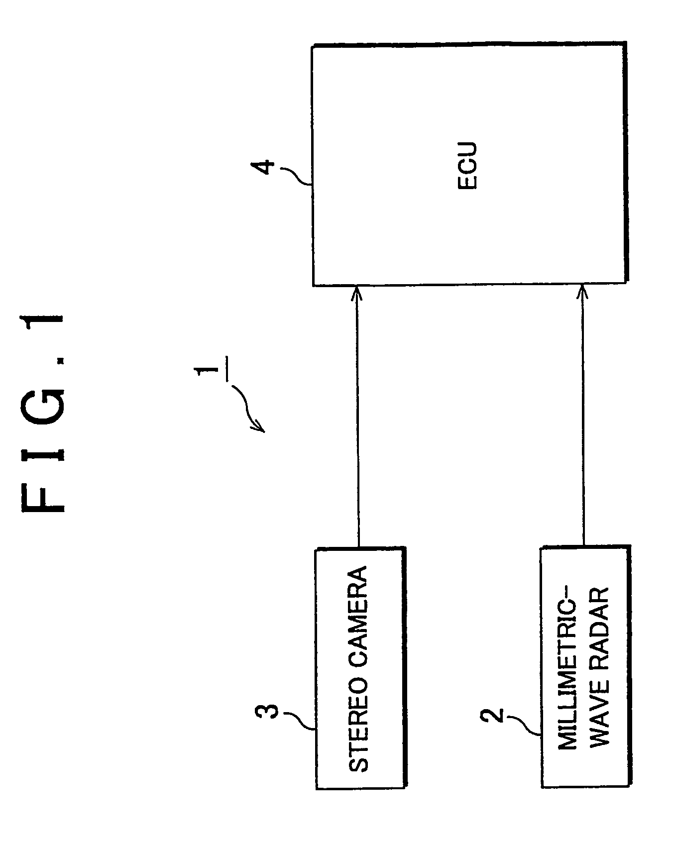
[0022] In this embodiment, the object detection system according to the invention is applied to an obstruction detection system provided in a vehicle so as to detect an obstruction that precedes the vehicle. The obstruction detection system in this embodiment is provided with two detection units, that is, a millimeter-wave radar and a stereo camera.

[0023] Referring to FIG. 1, an obstruction detection system 1 will be described. FIG. 1 shows a structure of the obstruction detection system according to this embodiment

[0024] The obstruction detection system 1 is provided in a vehicle to detect an obstruction, that is, a running vehicle or the like that precedes the vehicle. The obstruction detection system 1 functions in providing obstruction information to the operation support system, for example, a collision avoidance control system, an adaptive cruise contro...


PUM


Abstract

An object detection system includes a radar detection means (2), an image detection means (3), and a collating means (4). The collating means (4) performs a collation between an object detected by the radar detection means (2) in a present collation and an object that has been determined as being detected by the radar detection means (2) and the image detection means (3) in a previous collation (S 10, S 11), further performs a collation between an object detected by the image detection means (3) in a present collation and an object that has been determined as being detected by the radar detection means (2) and the image detection means (3) in the previous collation (S 12, S 13) when it is determined that the identical object is detected by the radar detection means (2) and the image detection means (3) in the previous collation. Then the collating means (4) determines whether the radar detection means (2) and the image detection means (3) detect the identical object based on the collations (S 14).

Description

BACKGROUND OF THE INVENTION [0001] 1. Field of Invention [0002] The invention relates to an object detection system that detects an object using radar and images. [0003] 2. Description of Related Art [0004] Recently an operation support system, for example, a collision avoidance control system, an adaptive cruise control system, a tracking control system and the like has been increasingly developed. The detection of an object (obstruction) such as a preceding vehicle is essential for the operation support system. An object detection system disclosed in publications JP-A-2003-84064 and JP-A-7-125567 as below includes two detection units, for example, a radar such as a laser radar, and a stereo camera that shoots an image. The object detection system performs collation between detection results of the radar and the detected image. The preceding object is detected based on the aforementioned collation results. [0005] In the generally employed object detection system using two kinds of ...

Claims


Application Information

Patent Timeline
IPC IPC(8): G01S13/86G01S13/89G01S13/931G01V11/00B60R1/00B60R21/00G01S11/12G01S13/72G01V3/12G01V8/10
CPCG01S11/12G01S13/726G01S13/931G01S13/867G01S2013/9375G01S2013/9321G01S2013/93271
Inventor ABE, KYOICHITOKORO, SETSUOSUZUKI, KOJI
Owner TOYOTA JIDOSHA KK
Learn More