Low loss electrode connection for inkjet printhead

Inactive Publication Date: 2007-04-12
ZAMTEC +1
View PDF19 Cites 58 Cited by
  • Summary
  • Abstract
  • Description
  • Claims
  • Application Information

AI Technical Summary

Benefits of technology

[0078] The conduits for distributing ink to every ink chamber in the array can occupy a significant proportion of the wafer area. This can be a limiting factor for nozzle density on the printhead. By making some ink chambers part of the ink flow path to other ink chambers, while keeping each chamber sufficiently free of fluidic cross talk, reduces the amount of wafer area lost to ink supply conduits.
[0079] For the purpose of increasing nozzle density it is also advantageous to use elongate actuators. Thinner actuators allow the ink chamber to be thinner and therefore the entire unit cell of the printhead to be smaller in one dimension at least. Accordingly adjacent nozz

Problems solved by technology

Larger contacts occupy a significant area of the w

Method used


Image

  • Low loss electrode connection for inkjet printhead
  • Low loss electrode connection for inkjet printhead
  • Low loss electrode connection for inkjet printhead

Examples


Embodiment Construction

[0438] In the description than follows, corresponding reference numerals relate to corresponding parts. For convenience, the features indicated by each reference numeral are listed below.

MNN MPN Series Parts List

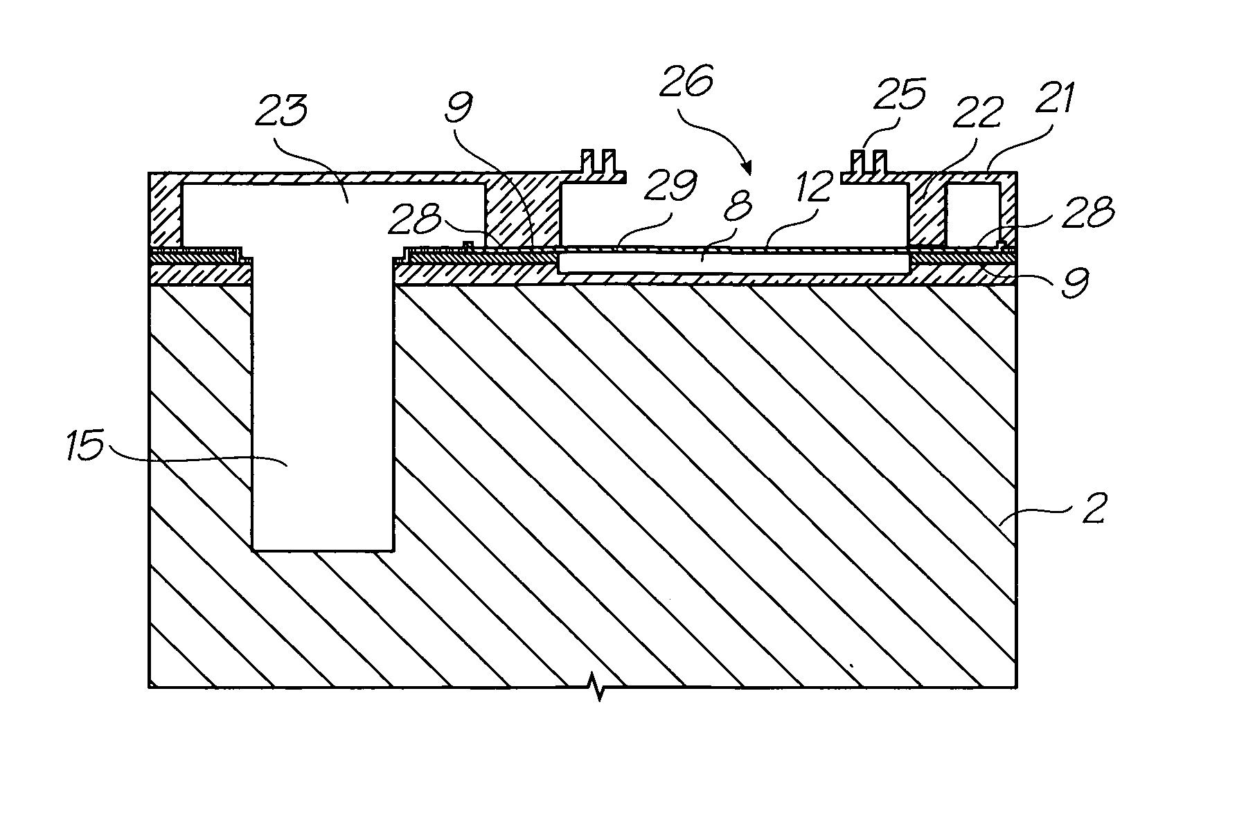
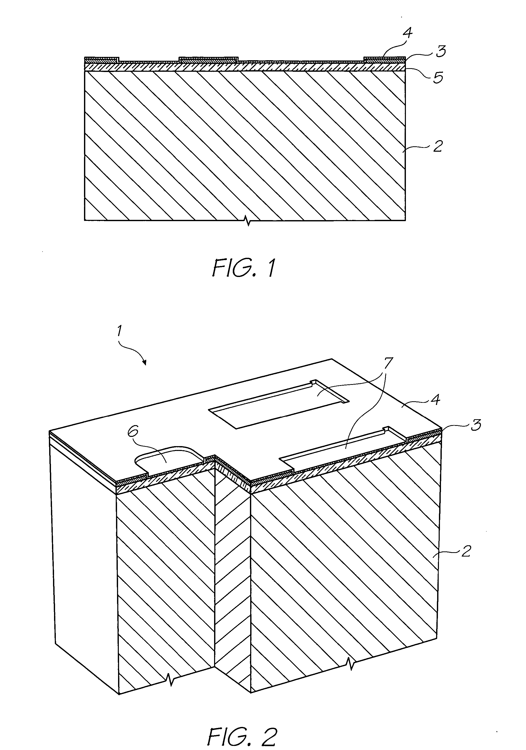
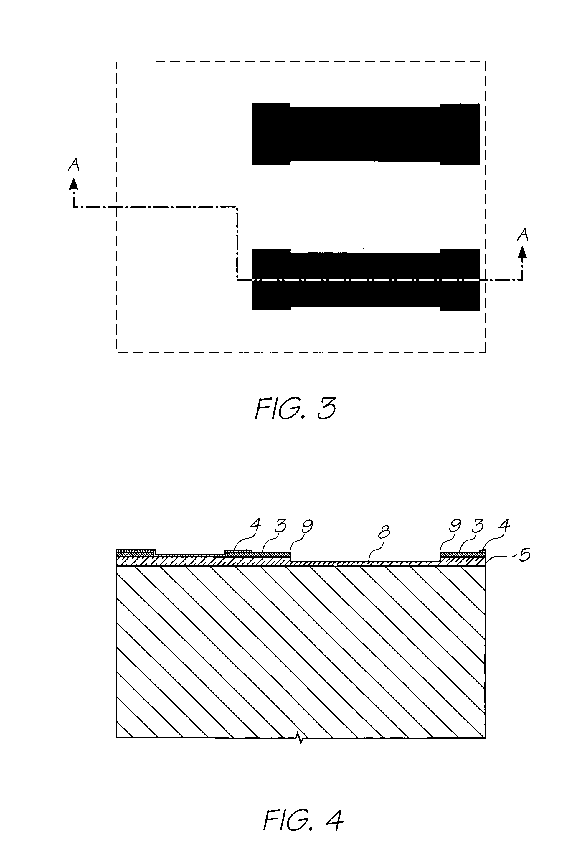
[0439]1. Nozzle Unit Cell [0440]2. Silicon Wafer [0441]3. Topmost Aluminium Metal Layer in the CMOS metal layers [0442]4. Passivation Layer [0443]5. CVD Oxide Layer [0444]6. ink Inlet Opening in Topmost Aluminium Metal Layer 3. [0445]7. Pit Opening in Topmost Aluminium Metal Layer 3. [0446]8. Pit [0447]9. Electrodes [0448]10. SAC1 Photoresist Layer [0449]11. Heater Material (TiAlN) [0450]12. Thermal Actuator [0451]13. Photoresist Layer [0452]14. Ink Inlet Opening Etched Through Photo Resist Layer [0453]15. Ink Inlet Passage [0454]16. SAC2 Photoresist Layer [0455]17. Chamber Side Wall Openings [0456]18. Front Channel Priming Feature [0457]19. Barrier Formation at Ink Inlet [0458]20. Chamber Roof Layer [0459]21. Roof [0460]22. Sidewalls [0461]23. Ink Conduit [0462]24. Nozzle...


PUM


Abstract

An inkjet printhead with planar thermal actuators, with contacts directly deposited onto the CMOS electrodes and suspended heater element, which avoids hotspots caused by vertical or inclined surfaces so that the contacts can be much smaller structures without acceptable increases in resistive losses. Low resistive losses preserves the efficient operation of a suspended heater element and the small contact size is convenient for close nozzle packing on the printhead.

Description

CROSS REFERENCES TO RELATED APPLICATIONS [0001] Various methods, systems and apparatus relating to the present invention are disclosed in the following U.S. patents / patent applications filed by the applicant or assignee of the present invention: 09 / 517539656685809 / 11276263319466246970644252509 / 51738409 / 505951637435409 / 51760809 / 50514710 / 20356467578326334190674533109 / 51754110 / 20355910 / 20356010 / 63626310 / 63628310 / 86660810 / 90288910 / 90283310 / 94065310 / 94285810 / 72718110 / 72716210 / 72716310 / 72724510 / 72720410 / 72723310 / 72728010 / 72715710 / 72717810 / 72721010 / 72725710 / 72723810 / 72725110 / 72715910 / 72718010 / 72717910 / 72719210 / 72727410 / 72716410 / 72716110 / 72719810 / 72715810 / 75453610 / 75493810 / 72722710 / 72716010 / 93472011 / 212,70210 / 296522679521510 / 29653509 / 57510910 / 29652509 / 57511009 / 607985639833263945736622923674776010 / 18945910 / 88488110 / 94394110 / 94929411 / 03986611 / 12301111 / 12301011 / 14476911 / 14823710 / 92284610 / 92284510 / 85452110 / 85452210 / 85448810 / 85448710 / 85450310 / 85450410 / 85450910 / 85451010 / 85449610 / 85449710 / 8544951...

Claims


Application Information

Patent Timeline
IPC IPC(8): B41J2/16B41J2/05B41J2/14
CPCB41J2/1404B41J2/14112B41J2/1603B41J2/1628B41J2/1631B41J2/1639B41J2/1642B41J2/1645B41J2002/14403B41J2002/14475
Inventor SILVERBROOK, KIA
Owner ZAMTEC
Why Eureka
Try Eureka