Display apparatus and method of controlling the same

Inactive Publication Date: 2007-04-12
SAMSUNG ELECTRONICS CO LTD
View PDF17 Cites 16 Cited by
  • Summary
  • Abstract
  • Description
  • Claims
  • Application Information

AI Technical Summary

Benefits of technology

[0008] Accordingly, it is an aspect of the present invention to provide a display apparatus for easily p

Problems solved by technology

Accordingly, it is currently necessary to provide a plurality of ICs for processing light emission-related i

Method used


Image

  • Display apparatus and method of controlling the same
  • Display apparatus and method of controlling the same
  • Display apparatus and method of controlling the same

Examples


Embodiment Construction

[0026] Reference will now be made in detail to exemplary embodiments of the present invention, examples of which are illustrated in the accompanying drawings.

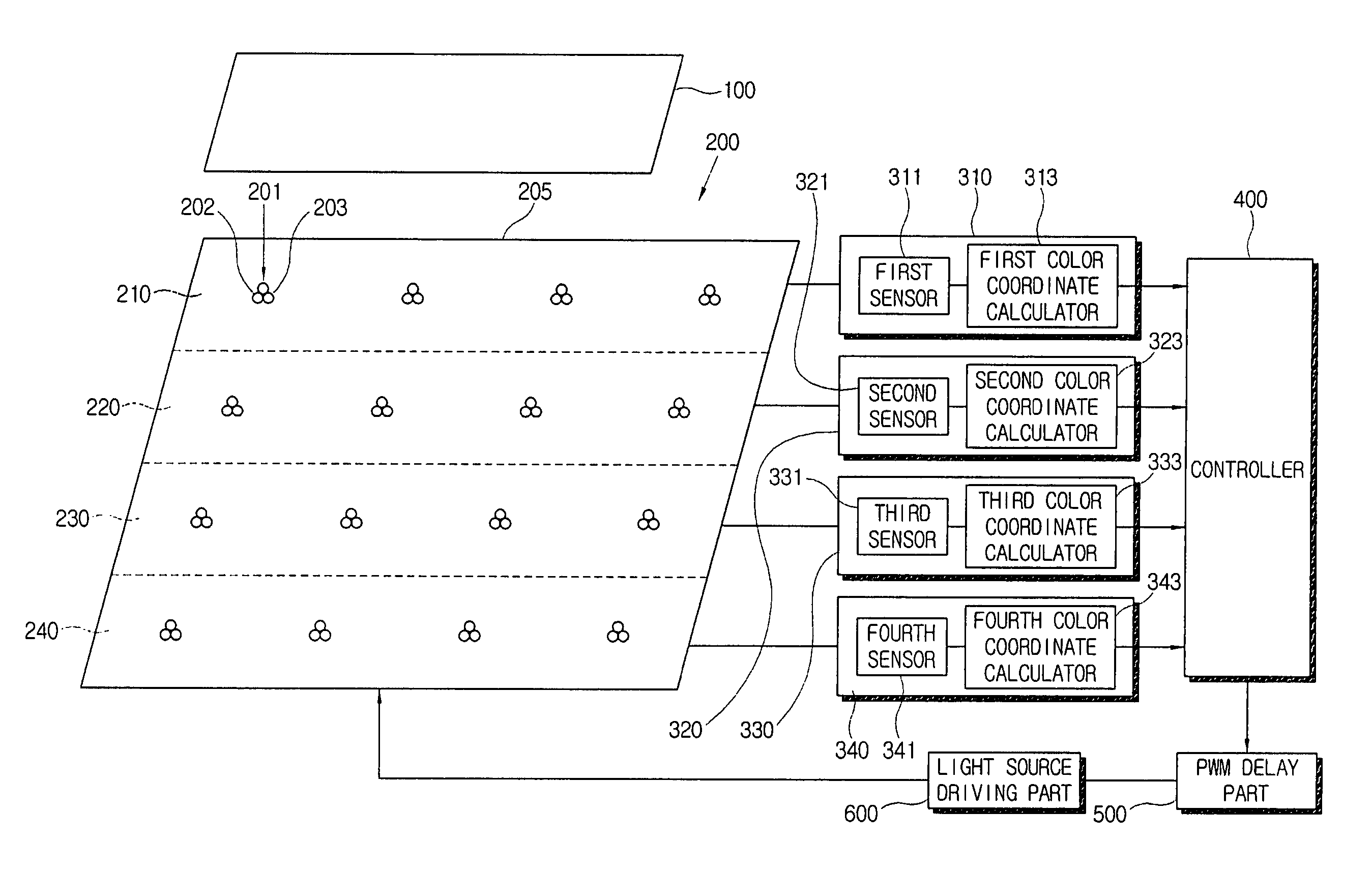
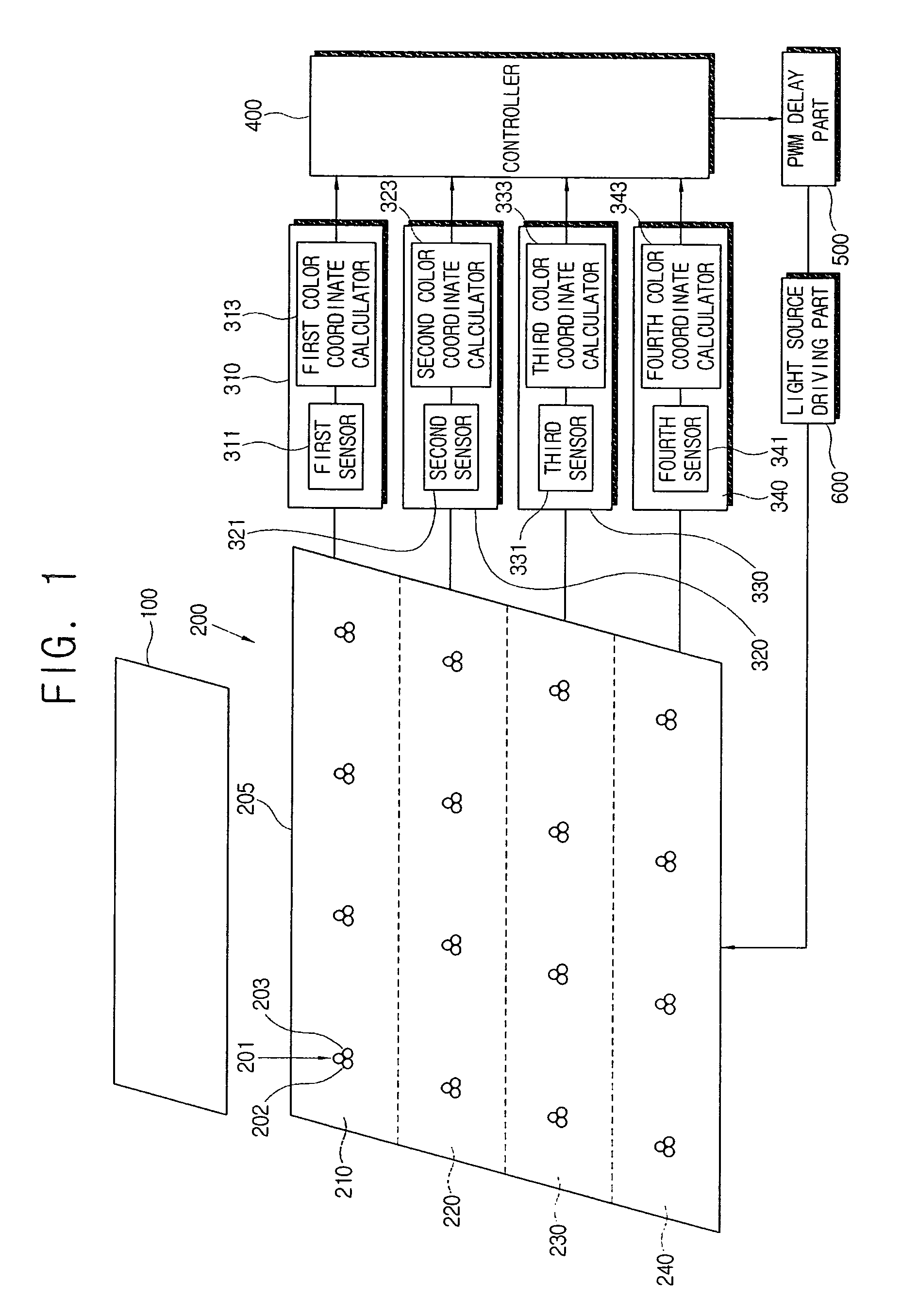
[0027]FIG. 1 is a control block diagram of a display apparatus according to an exemplary embodiment of the present invention. As shown in FIG. 1, a display apparatus includes a liquid crystal panel 100, a light source part 200, a channel part 300, a controller 400, a PWM delay part 500, and a light source driving part 600.

[0028] Although not shown in the figure, the liquid crystal panel 100 preferably includes a thin film transistor substrate with a plurality of transistors formed thereon, a color filter substrate facing the thin film transistor substrate, a sealant bonding both substrates together and forming a cell gap, and a liquid crystal layer placed between both substrates and the sealant. In this embodiment, the liquid crystal panel 100 has a rectangular form with long sides and short sides.

[0029] The liquid crystal p...


PUM


Abstract

A display apparatus having a liquid crystal panel, comprises a light source part comprising a plurality of point light sources for supplying light to the liquid crystal panel. The light source part is partitioned into a plurality of light source zones. A light source driving part supplies power to the light source part. A plurality of channel parts sense luminescence of the point light sources for each of the light source zones and output light-emission information of the point light sources based on the sensed luminescence. A controller compares the light-emission information output from the plurality of channel parts with a pre-set reference value. If a difference between the light-emission information and the reference value is out of a predetermined allowable range, the controller sequentially adjusts PWM control signals which are output to the light source driving part, for each of the light source zones.

Description

CROSS-REFERENCE TO RELATED APPLICATIONS [0001] This application claims the benefit under 35 U.S.C. §119(a) of Korean Patent Application No. 2005-0095789, filed on Oct. 2, 2005, the entire disclosure of which is hereby incorporated by reference. BACKGROUND OF THE INVENTION [0002] 1. Field of the Invention[0003] The present invention relates to a display apparatus and a control method of the same. More particularly, the present invention relates to a display apparatus having a plurality of light-emitting elements as a light source, and a method of controlling the same. [0004] 2. Description of the Related Art [0005] Display apparatuses are increasingly employing LEDs (Light-Emitting Diodes) rather than conventional CCFLs (Cold Cathode Fluorescent Diodes) as point light sources in order to improve the reproduction of colors. [0006] Recently, as display apparatuses become larger in size, there is an increasing need to dispose a plurality of light sources in a plurality of regions within...

Claims


Application Information

Patent Timeline
IPC IPC(8): F21V7/04
CPCG02F1/133603G02F2001/133613G09G3/3413G09G3/342G09G3/3648G09G2310/024G09G2310/061G09G2320/064G09G2320/0666G09G2360/145G02F1/133613G02F1/133
Inventor KIM, SUNG-SOOPARK, YUNG-JUNSUNG, JUN-HO
Owner SAMSUNG ELECTRONICS CO LTD
Why Eureka
Try Eureka