

Pneumatic retractable self-destructing injection device
- Summary
- Abstract
- Description
- Claims
- Application Information
AI Technical Summary
Benefits of technology
Problems solved by technology
Method used
Image

Examples
embodiment 1
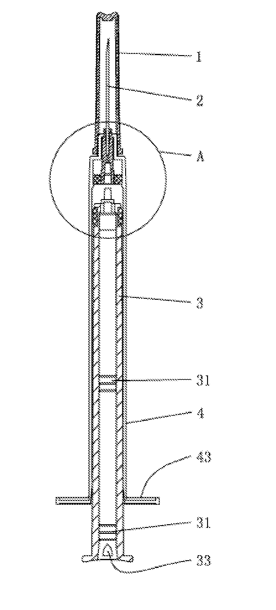
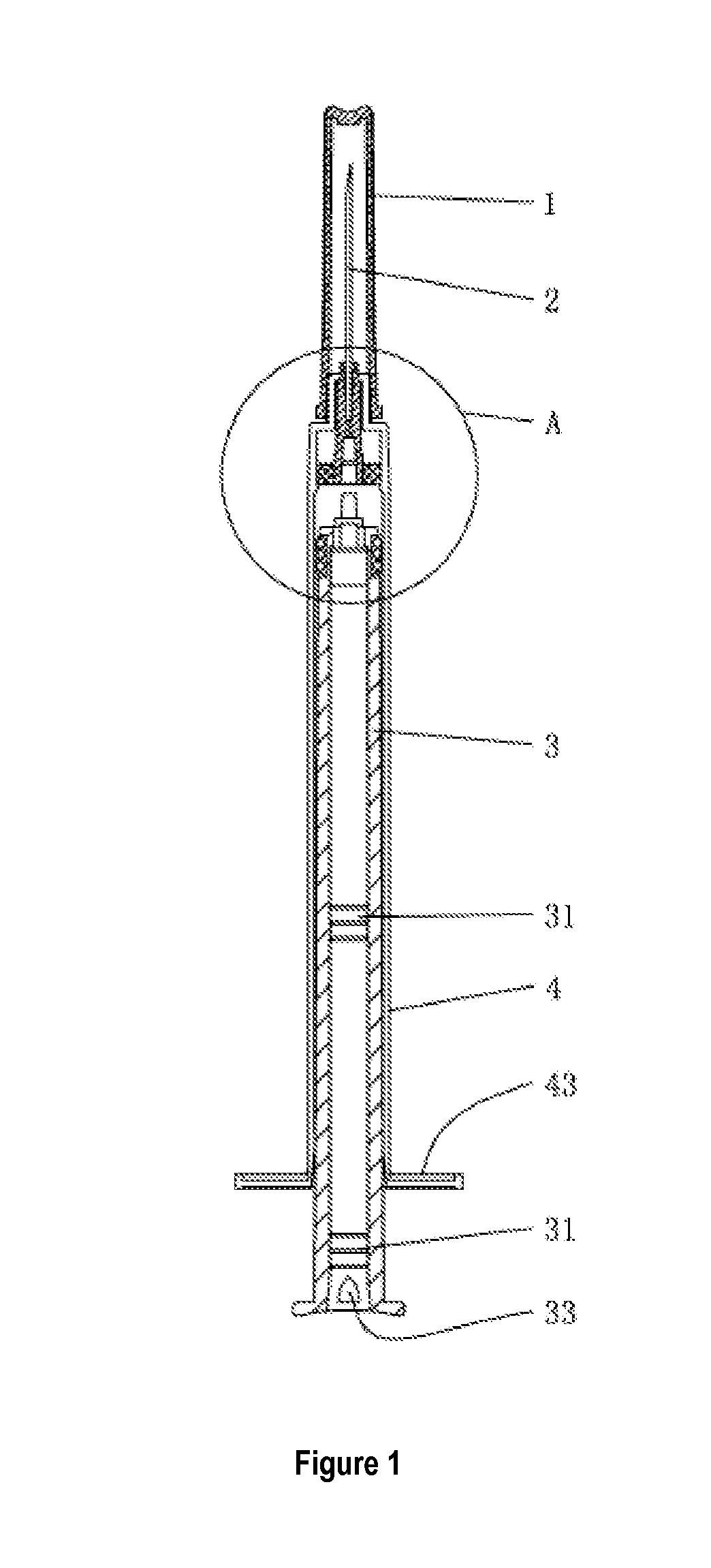
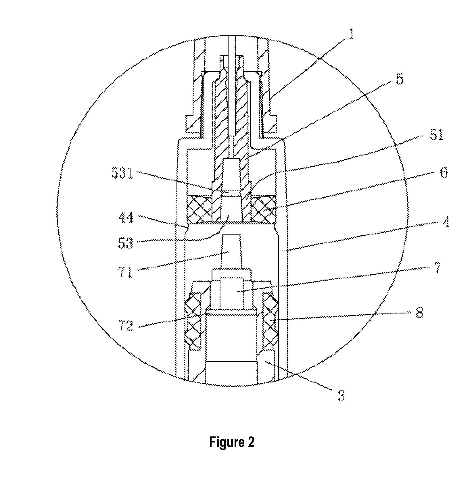
[0027]FIGS. 1˜6 illustrate a pneumatic retractable auto-disable syringe comprising a syringe barrel 4, a hollow cylindrical plunger 3, a needle hub 5, a sealing ring 6, a piston 8 and a seal connector 7, wherein: the needle hub 5 is provided with a needle 2 centrally disposed thereon, the needle hub 5 is mounted at the front end of the syringe barrel 4 after passing through the sealing ring 6 located therebeneath, the piston 5 is disposed on the outer side of the plunger 3 at the front end thereof, the seal connector 7 is disposed on the inner side of the plunger 3 at the front end thereof, the seal connector 7 and the needle hub 5 are provided with a compatible connection mechanism disposed thereon, characterized in that: when the plunger 3 is pushed to the front end of the syringe barrel 4, the inner wall of the syringe barrel 4 at the front end thereof and the outer wall of the needle hub 5 at the front end thereof are pneumatically sealed; the plunger 3 is provided with a positi...
embodiment 2
[0036]As shown in FIGS. 7˜8, this embodiment is basically identical to Embodiment 1. The differences between the two are: the position limiting device on the plunger 3 is a narrow mouth 34 formed on the inner wall thereof, and a transitional bevel is disposed between the upper side of the narrow mouth 34 and the inner wall of the plunger 3; a bottom cover 9 is embedded in the plunger at the bottom portion thereof, and the air vent 33 for air exchange between the inner cavity of the plunger 3 and the outside is bar-shaped. After auto-disablement of the syringe, the seal connector 7 and the needle hub 5 are located between the narrow mouth 34 and the bottom cover 9.
PUM
 Abstract
Description
Claims
Application Information