

Valve
- Summary
- Abstract
- Description
- Claims
- Application Information
AI Technical Summary
Benefits of technology
Problems solved by technology
Method used
Image

Examples
first embodiment
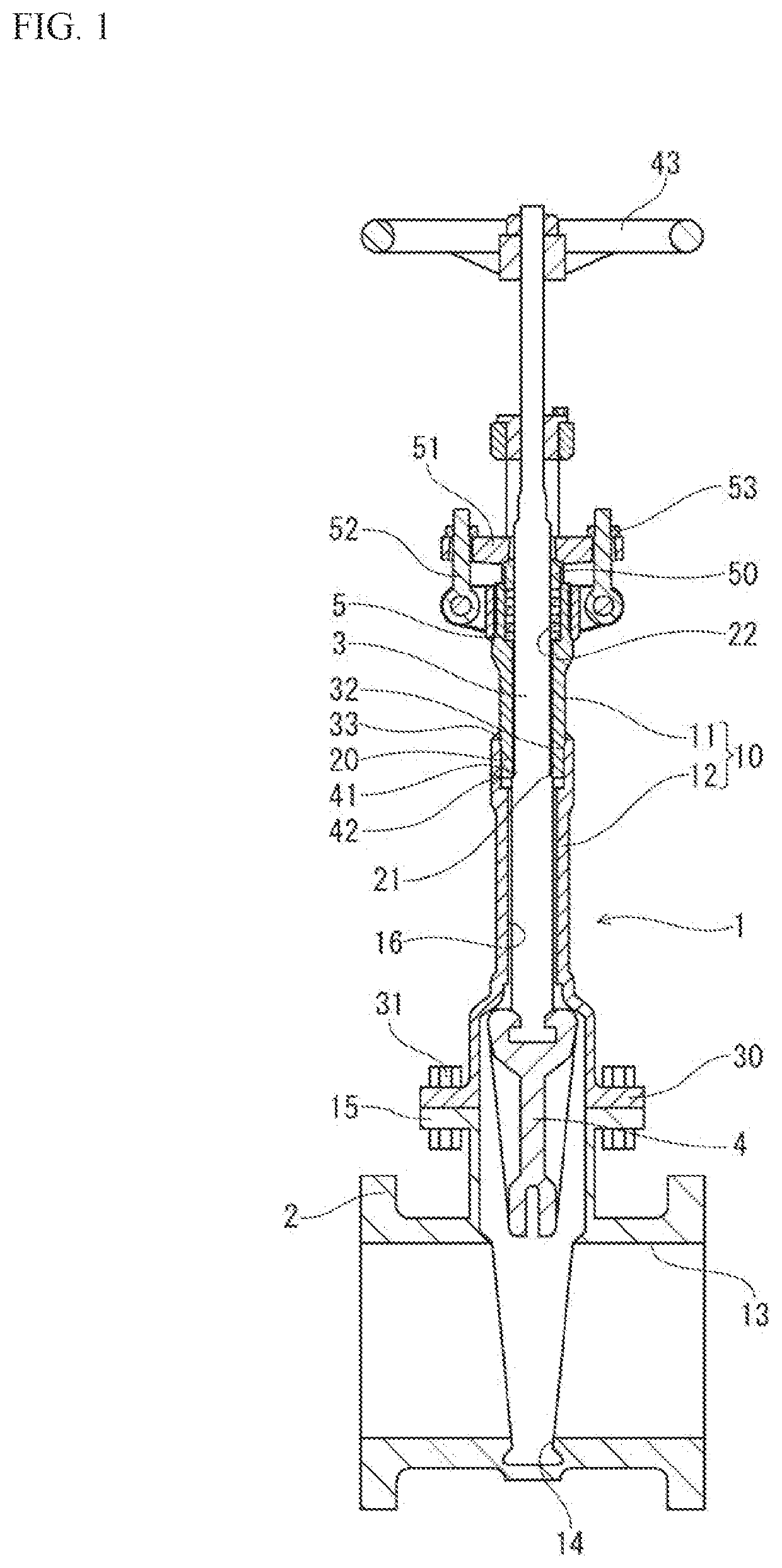
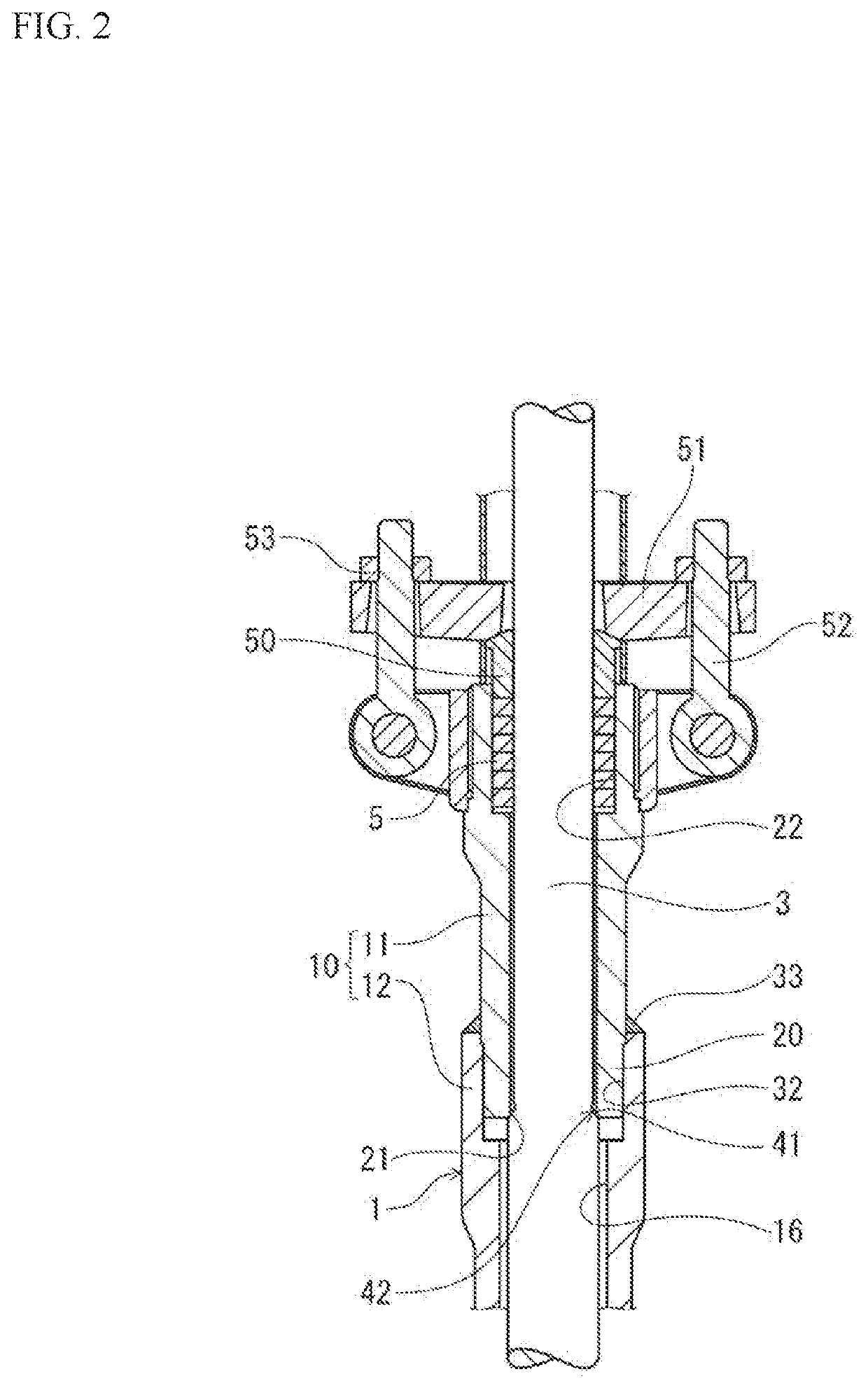
[0044]In the following, the valve of the present invention is described in detail based on embodiments. Depicted in FIG. 1 is the valve, and depicted in FIG. 2 is an enlarged sectional view of main parts of FIG. 1. The valve (hereinafter referred to as a valve main body 1) of the present invention is formed of an on-off valve of a gate valve, and has a valve box 2, a stem 3, a valve body 4, a packing 5, and a bonnet 10. The bonnet 10 is provided to have a longneck structure in an extending shape having an upper bonnet 11 and a lower bonnet 12, which will be described further below. This bonnet 10 prevents freezing of a gland portion against an ultralow-temperature fluid such as LNG, allowing the ultralow-temperature fluid to flow by opening and closing of the valve body 4.
[0045]As depicted in FIG. 1, the valve box 2 is formed of a metal material having low-temperature resistance such as, for example, a stainless material. Inside this valve box, a straightly-shaped flow path 13 is pr...
fifth embodiment
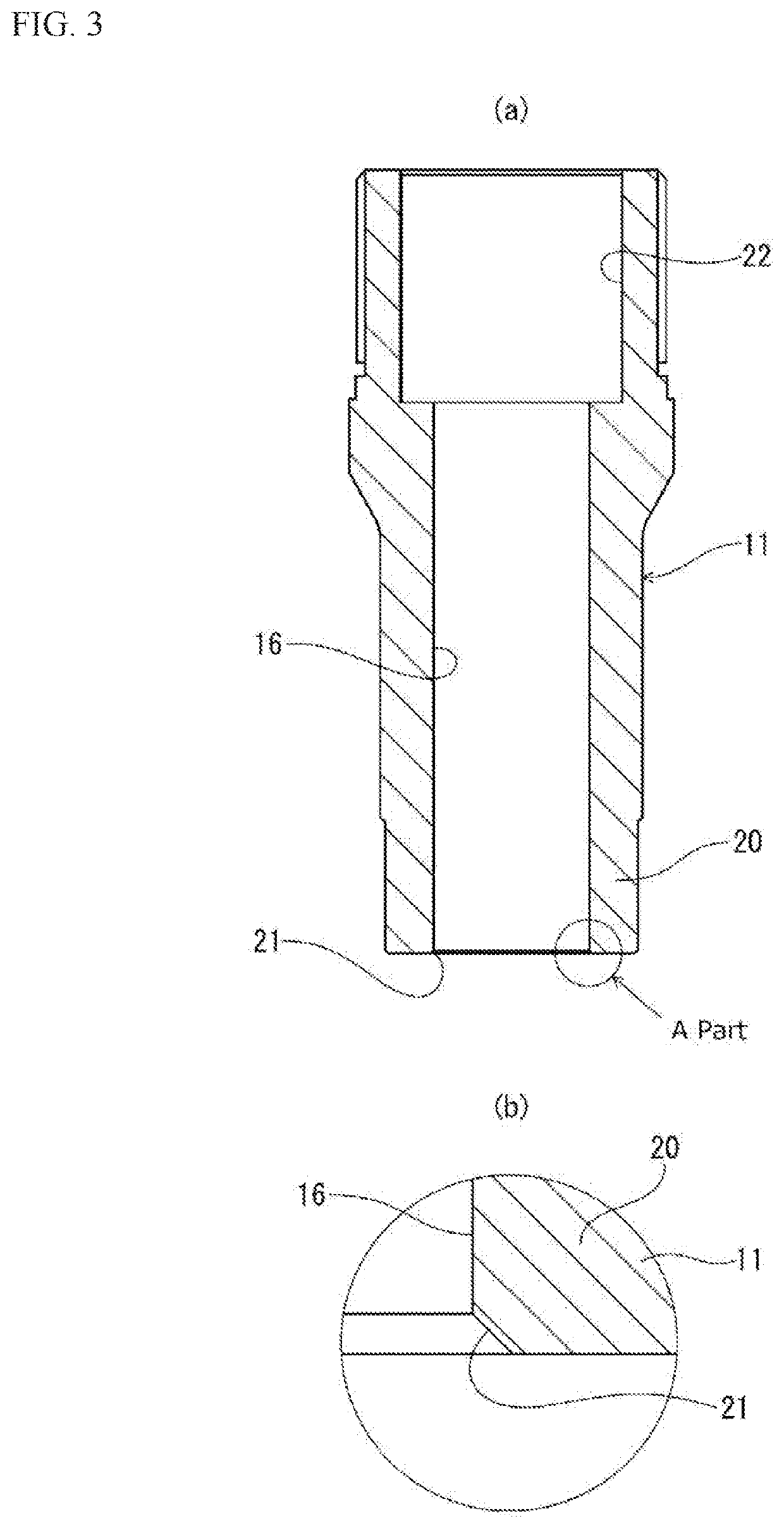
[0054]Also, in the present example, a lower side of the upper bonnet 11 as the insertion part 20 is inserted into the lower bonnet 12, and a tip on the lower side of this upper bonnet 11 serves as the fixed-side seal surface 21. That is, the fixed-side seal surface 21 of the upper bonnet 11 is shaped with its perimeter wrapped by an upper opening of the lower bonnet 12. When a backseat mechanism 42 functions, a movable-side seal surface 412 provided to the stem 3 abuts on the tapered fixed-side seal surface 21 opening downward. Thus, to the fixed-side seal surface 21, a force to open outward is applied. However, according to the present example, the fixed-side seal surface 21 has its periphery wrapped by the lower bonnet 12, and is thus sufficiently resistant to the force opening outward and can stably exert a function as a backseat. Note that even if the lower bonnet 12 is not necessarily present on the periphery of the fixed-side seal surface 21, with the insertion part of the upp...
second embodiment
[0074]Depicted in FIG. 5 is the valve of the present invention. Note that in this embodiment onward, the same portion as that of the above-described embodiment is represented by the same reference character and its description is omitted.
[0075]In this valve (valve main body 60), the movable-side seal surface 41 is integrally formed on the stem 3. On the other hand, a seal member 61 is provided separately from the upper bonnet 11. The seal member 61 is attached below the upper bonnet 11, and a fixed-side seal surface 62 is formed on an inner peripheral surface side at a lower end of this seal member 61.
[0076]The seal member 61 is provided by a metal material or a resin material, or a combination of both of these. For example, it is annularly formed of a metal sheet by a copper alloy, or in a shape with less seat deformation by a soft seat made of PTFE or PCTFE.
[0077]The seal member 61 is attached in a narrowly-attached state or a loosely-fitting state between a lower end face 11a of ...
PUM
 Abstract
Description
Claims
Application Information