High bitrate transport over multimode fibers

a multi-mode fiber and high-bitrate technology, applied in the field of mode couplers, can solve the problems of difficult high-speed transmission, and achieve the effects of increasing the effective bandwidth of multi-mode fiber, high speed, and greater distan

Active Publication Date: 2007-04-12
ANALOG DEVICES INC
View PDF16 Cites 28 Cited by
  • Summary
  • Abstract
  • Description
  • Claims
  • Application Information

AI Technical Summary

Benefits of technology

[0008] With the help of this invention effective bandwidth of multimode fiber is increased which results in greater distance that high speed data may be transmitted without modal dispersion.

Problems solved by technology

These modes travel at different speeds and thus high speed transmission becomes difficult due to overlap of data pulses after traveling some distance in the fiber.

Method used


Image

  • High bitrate transport over multimode fibers
  • High bitrate transport over multimode fibers
  • High bitrate transport over multimode fibers

Examples


Embodiment Construction

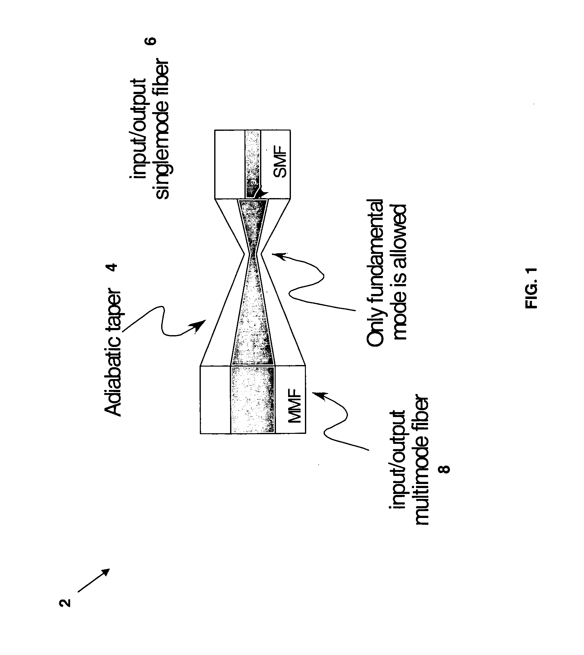
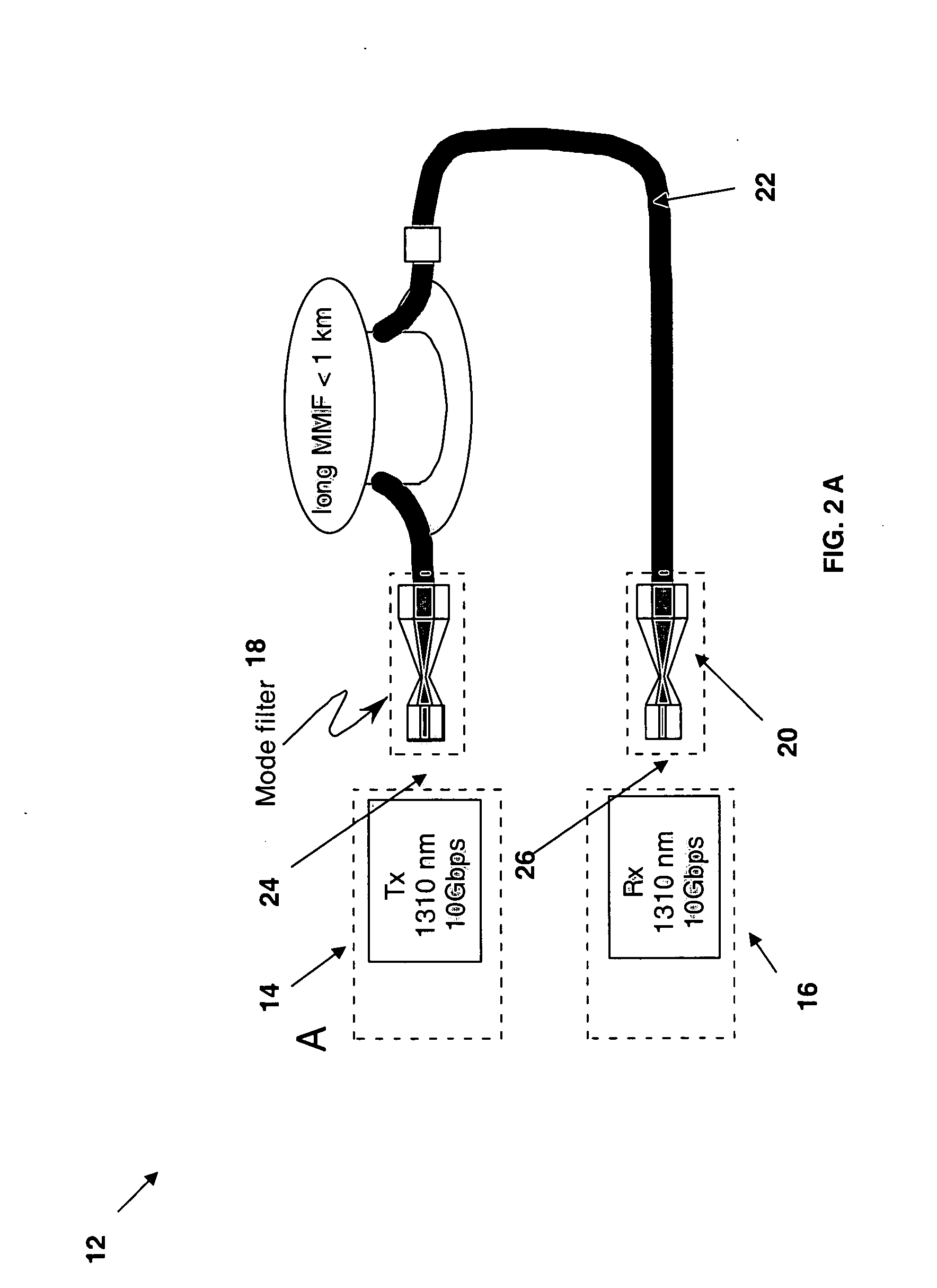
[0013] The invention attempts to increase the effective bandwidth (EB) of a MM fiber by simultaneously using (i) a special form of restricted mode launch from the transmitter and (ii) an optical filter at the output that passes only a specific set of fiber modes and filters out the unwanted modes before the optical signal is detected by a photodiode. The optical filter at the output is an example of a complex linear filter such that any linear combination of the modes of the fiber may be selected at the transmitter for excitation and at the receiver for filtering before detection.

[0014] The simplest method to implement the concept outlined above would be to excite only a fundamental mode of the fiber which is traditionally designated as LP01. This is a linearly polarized mode and can be predominantly excited in the fiber with an appropriately matched Gaussian beam. A Gaussian beam will be used having the definition of waist w as EG⁡(r)=ⅇ-(rw)2EQ. ⁢1

[0015] The waist w can be chosen...


PUM


Abstract

A multimode fiber system includes a transmitter for transmitting an optical signal and a receiver that receives the optical signal. At least one mode filter is coupled between the receiver and the transmitter and passes only a specific set of fiber modes from the transmitter to be received by the receiver. The at least one mode filter comprises a tapered core section that includes a double taper configuration joined at the narrowest regions and in which each end of the two tapers has dimensions compatible with the fiber at that end.

Description

PRIORITY INFORMATION [0001] This application claims priority to provisional application Ser. No. 60 / 719,107 filed Sep. 21, 2005, and to U.S. patent applications Ser. Nos. 10 / 988,778, filed Nov. 15, 2004, and Ser. No. 11 / 056,890, filed Feb. 11, 2005, all of which are incorporated herein by reference in their entireties.BACKGROUND OF THE INVENTION [0002] The invention relates to the field of mode couplers used in receivers, and in particular the invention allows use of external simple patch cords to enable 10 G and higher bitrate over glass and plastic multimode fibers. [0003] Most long distance fiber links greater than 200-300 m use lasers with the wavelengths greater than 1200 nm and specifically at the wavelengths around 1310 nm, 1490 nm, 1510-1570 nm, and 1620 nm. These links also employ single mode fibers with core diameter of approximately 8 μm. On the other hand, fiber links less than 200 m for short reach communications are often dominated by a wavelength around 850 nm and use...

Claims


Application Information

Patent Timeline
Patent Type & Authority Applications(United States)
IPC IPC(8): G02B6/26
CPCG02B6/02052G02B6/1228G02B6/14G02B6/305H04B10/2581G02B6/0288G02B6/264
Inventor DELIWALA, SHRENIK
Owner ANALOG DEVICES INC
Why Eureka
Try Eureka