
Signal generation apparatus, frequency converting apparatus, and receiver

a signal generation and frequency conversion technology, applied in the field of semiconductor devices, can solve the problem of reducing the magnitude of the qa signal to the size of the qc signal

Inactive Publication Date: 2007-04-12
SAMSUNG ELECTRONICS CO LTD
View PDF6 Cites 12 Cited by
  • Summary
  • Abstract
  • Description
  • Claims
  • Application Information

AI Technical Summary

Benefits of technology

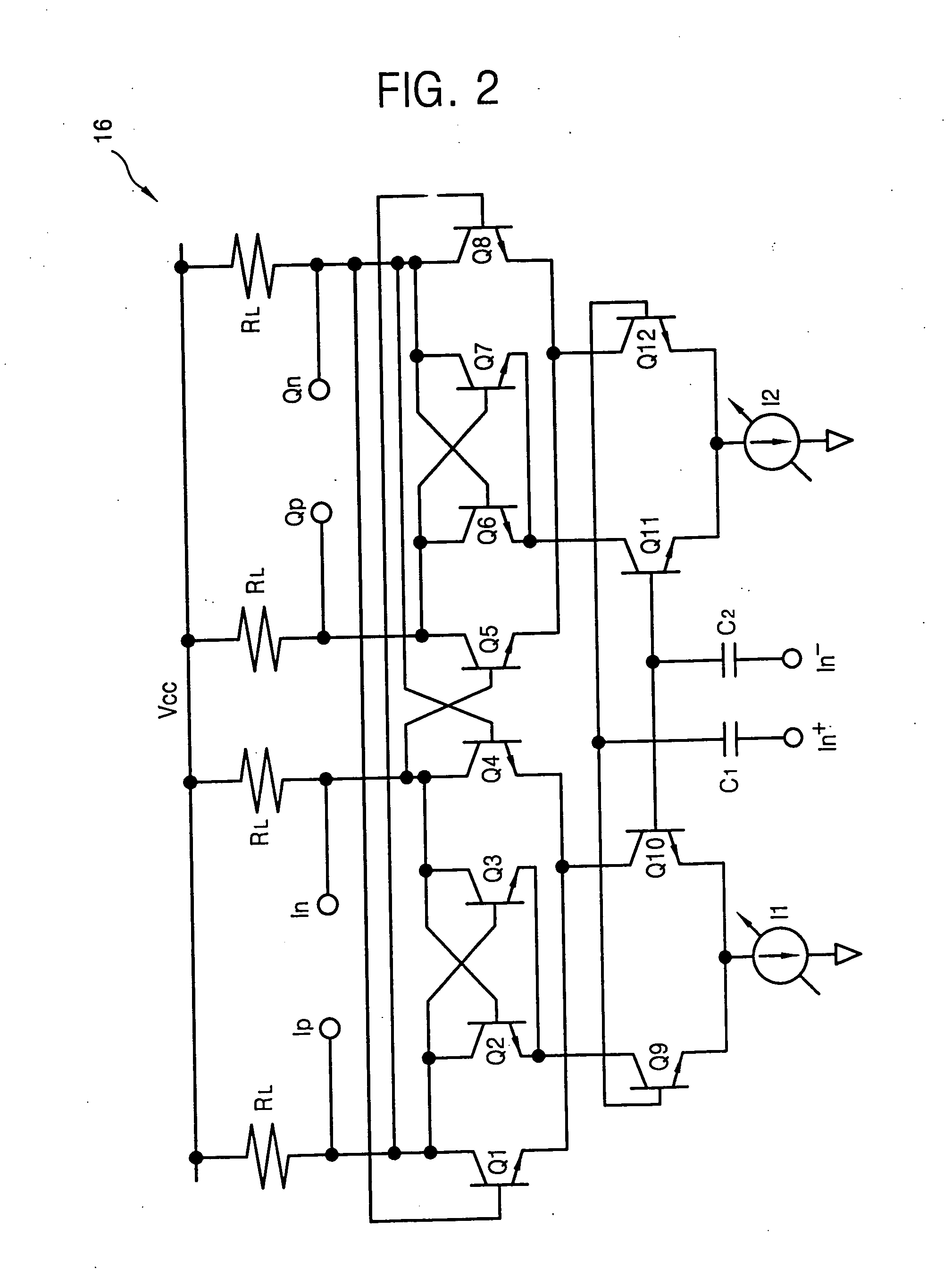
[0024] According to an embodiment of the present invention, there is provided a method of generating signals. The method includes generating differential signals; adjusting the duty cycles of the differential signals in order to adjust phases of the differential output signals generated according to a result of amplifying a difference between the differential signals which were input in response to a corresponding control signal; outputting the duty cycle adjusted differential output signals; and generating at least one of the in-phase signals and one of the quadrature-phase signals, respectively, in response to the duty cycle adjusted differential output signals.
[0025] According to an embodiment of the present invention, there is provided a method of converting a frequency. The method includes generating the differential signals; adjusting the duty cycles of the differential output signals in order to adjust a phase of the differential output signals generated according to a result of amplifying a difference between the differential signals which were input in response to a corresponding control signal; outputting the duty cycle adjusted differential output signals to a pair of output terminals; outputting the in-phase signal and the quadrature-phase signal in response to the duty cycle adjusted differential output signal; receiving the In-phase signals output from the radio input signal and the signal generation circuit and mixing them; and outputting first and second intermediate frequency signals according to the mixing result.

Problems solved by technology

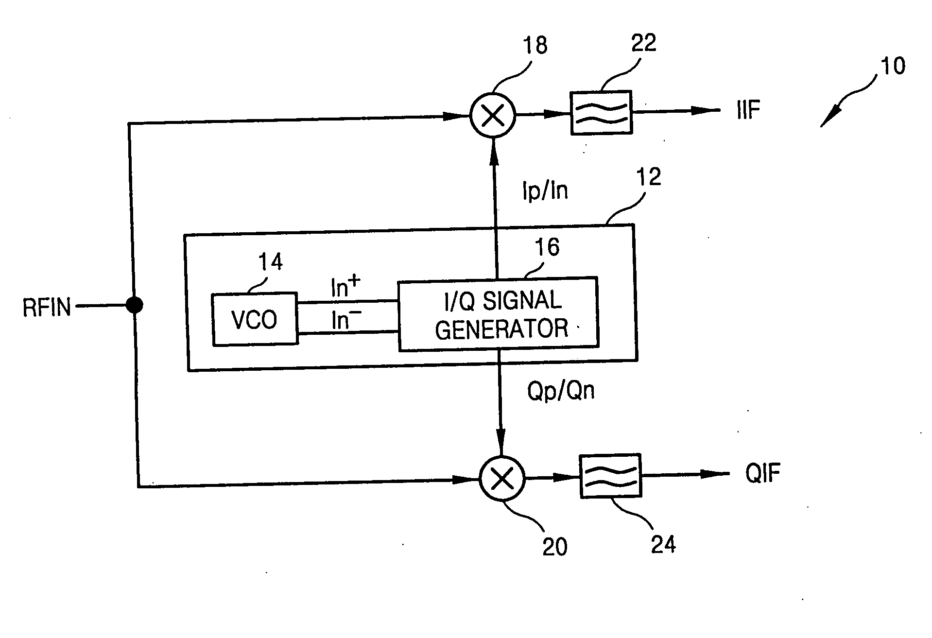
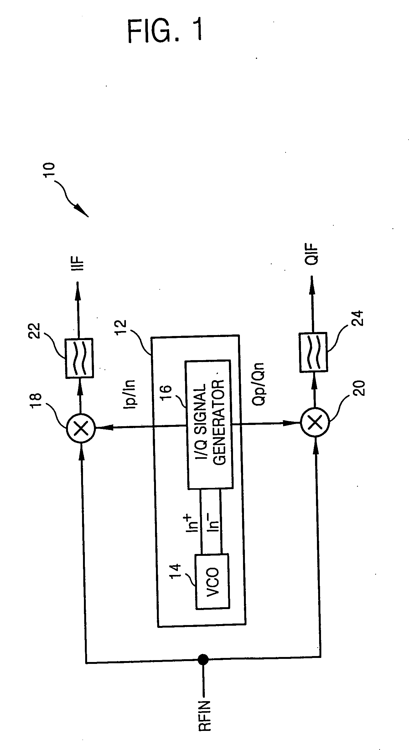
But, this method can involve a problem illustrated in FIG. 3.
When the QA signal is compensated by changing the operation speed, the phase difference between the I signal and a QC signal may be adjusted to 90°, but there still is a problem that the magnitude of the QA signal is reduced to a size of the QC signal.

Method used


Image

  • Signal generation apparatus, frequency converting apparatus, and receiver
  • Signal generation apparatus, frequency converting apparatus, and receiver
  • Signal generation apparatus, frequency converting apparatus, and receiver

Examples


Embodiment Construction

[0036] Exemplary embodiments of the present invention are described more fully hereinafter with reference to the attached drawings, wherein like reference numerals refer to the like elements throughout.

[0037]FIG. 4 is a block diagram of a frequency converting apparatus according to an embodiment of the present invention. Refering to FIG. 4, the frequency converting apparatus 100 includes a signal generation apparatus 110, a first mixer 152, and a second mixer 154.

[0038] The frequency converting apparatus 100 may further include a first filter 156 and a second filter 158. A receiver (not illustrated) employing the frequency converting apparatus 100 includes an antenna(not illustrated) for receiving an input signal (RFIN).

[0039] The signal generation apparatus 110 adjusts duty cycles of the differential output signals for adjusting phases of the differential signals generated according to a result of amplifying a difference between the differential signals Din+ and DIn− in response...


PUM


Abstract

A signal generation apparatus, a frequency converting apparatus and a receiver, in which the signal generation apparatus includes an oscillator, a duty cycle adjusting circuit, and a signal generation circuit. The oscillator generates differential signals. The duty cycle adjusting circuit adjusts duty cycles of differential output signals, in response to at least one of a plurality of control signals, to adjust phases of the differential output signals generated according to a result of amplifying a difference between the differential signals input through a pair of input terminals so as to output duty cycle adjusted differential output signals to a pair of output terminals. The signal generation circuit outputs an in-phase signal and a quadrature-phase signal in response to the duty cycle adjusted differential output signals. The frequency converting apparatus includes a first mixer for mixing an input signal with the in-phase signal and a second mixer for mixing the input signal and the quadrature-phase signal.

Description

PRIORITY STATEMENT [0001] This non-provisional application claims priority under 35 U.S.C. 119 to Korean Patent Application No. 10-2005-0094259, filed on Oct. 7, 2005, in the Korean Intellectual Property Office (KIPO), the entire contents of which are incorporated herein by reference. BACKGROUND OF THE INVENTION [0002] 1. Technical Field [0003] The present disclosure relates to semiconductor devices and, more particularly, to a signal generation apparatus generating I / Q signals having a phase difference of 90° and signal generation method, a frequency converting appratus including the signal generation appratus and a frequency converting method, and a receiver including the frequency converting apparatus. 2. Discussion of the Related Art Generally, a Zero-IF structure and an image-rejection structure which are widely used as a receiver structure characteristically require an In-phase signal, hereinafter an ‘I signal’, and a Quadrature-phase signal, hereinafter a ‘Q signal’. The I si...

Claims


Application Information

Patent Timeline
Patent Type & Authority Applications(United States)
IPC IPC(8): H04B1/40H04B1/06
CPCH03B27/00H03C1/36H03F3/4508H03F3/45089H03F2200/336H03F2203/45302H03F2203/45318H03F2203/45352H03F2203/45366H03F2203/45466H03F2203/45544H03K5/1565H04B1/06H04B1/40
Inventor KIM, HYUN-SEOK
Owner SAMSUNG ELECTRONICS CO LTD
Learn More