Frequency Hopping System and Method for Communicating with RFID Tags

a frequency hopping system and tag technology, applied in the field of radio frequency re identification (rfid) transponders, can solve the problems of limiting the usefulness of such transponders, consuming more and more power, and consuming new functions and desired, etc., and achieve the effect of reducing the time taken to identify the tag or tag

Inactive Publication Date: 2007-04-19
PILLAI VIJAY +3
View PDF0 Cites 8 Cited by
  • Summary
  • Abstract
  • Description
  • Claims
  • Application Information

AI Technical Summary

Benefits of technology

[0015] It is an object of the invention to produce a method, an apparatus, and a system communicating between a base station and at least one tag which decreases the time taken to identify the tag or tags.

Problems solved by technology

However, the usual problems with life and expense limit the usefulness of such transponders.
However, the new functions allowed and desired consume more and more power, even though the individual components consume less power.
However, such means require use of possibly two tag antennas or more complicated electronics.
If the number of possible tags in the field is large, this process can take a very long time.
If the power reception is interrupted for a length of time which exceeds the energy storage time of the tag power supply, the tag “loses” the memory that it was turned off from communication, and will restart trying to communicate with the base station, and interfere with the orderly communication between the base station and the multiplicity of tags.
The amount of power that can be broadcast in each RF band is severely limited by law and regulation to avoid interference between two users of the electromagnetic spectrum.
One limit is a limit on the continuously radiated power in a particular bandwidth, and another limit is a limit on peak power.

Method used


Image

  • Frequency Hopping System and Method for Communicating with RFID Tags
  • Frequency Hopping System and Method for Communicating with RFID Tags
  • Frequency Hopping System and Method for Communicating with RFID Tags

Examples


Embodiment Construction

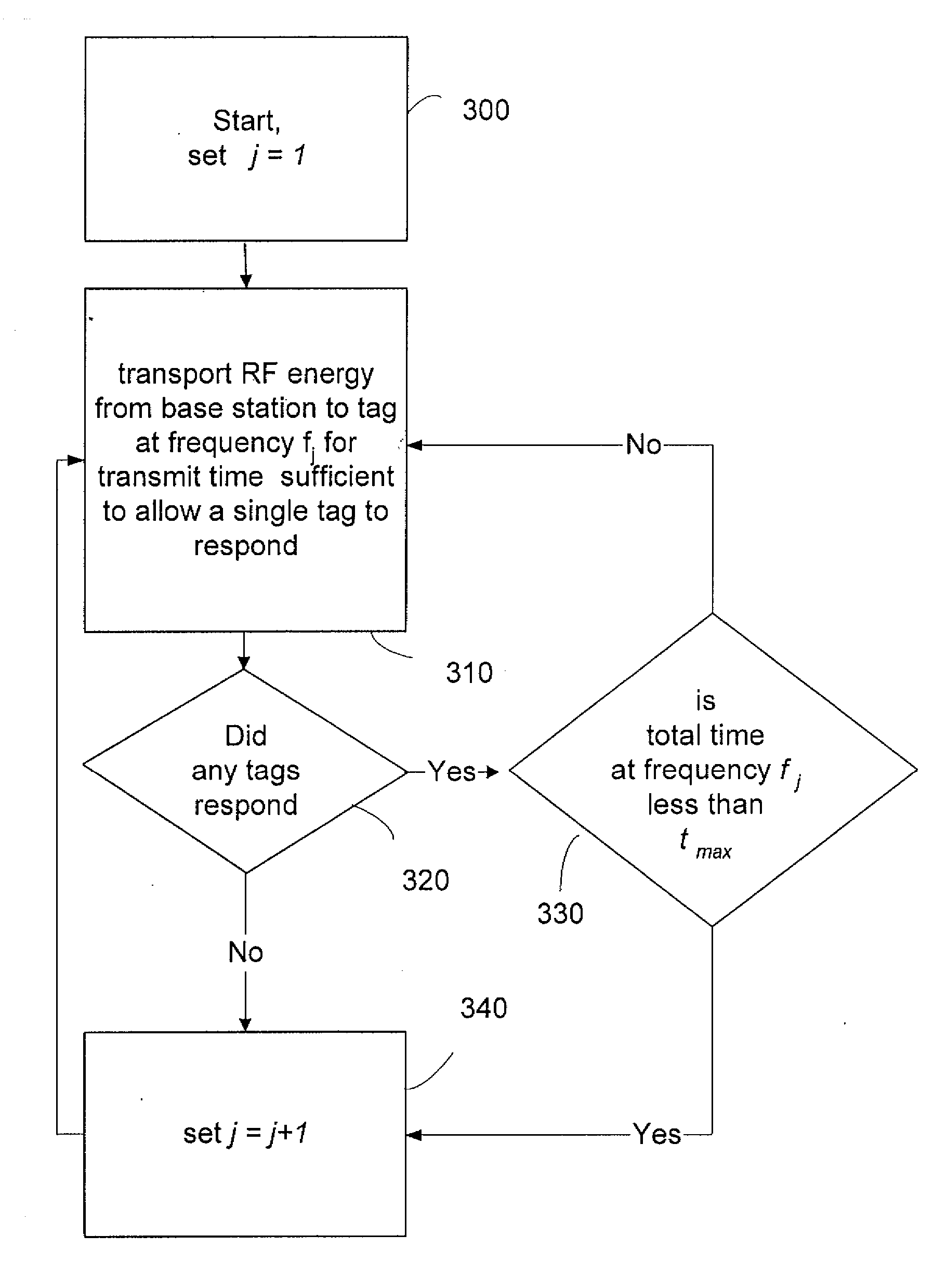
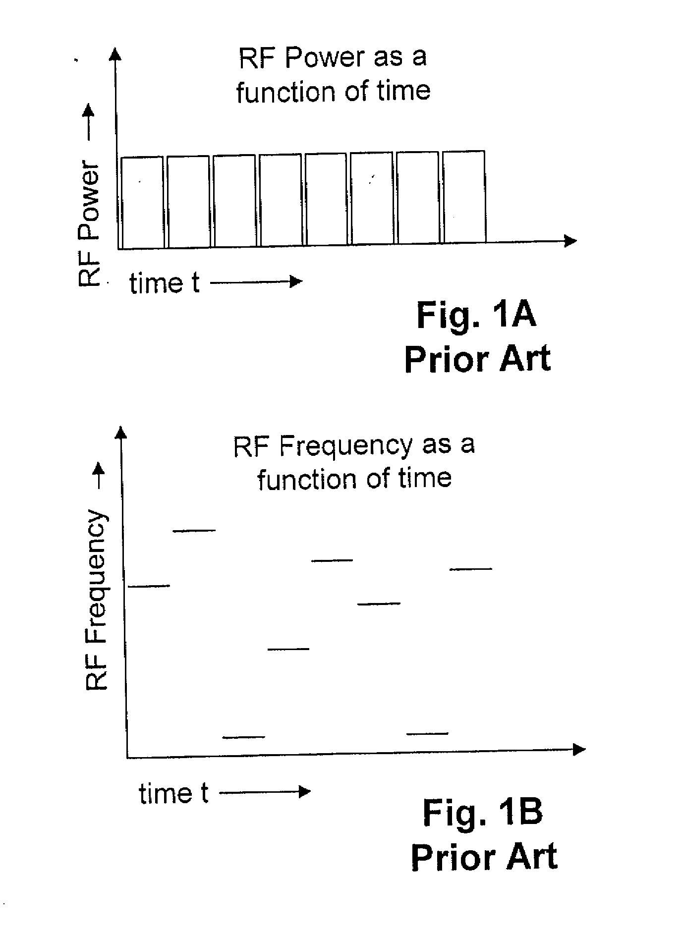
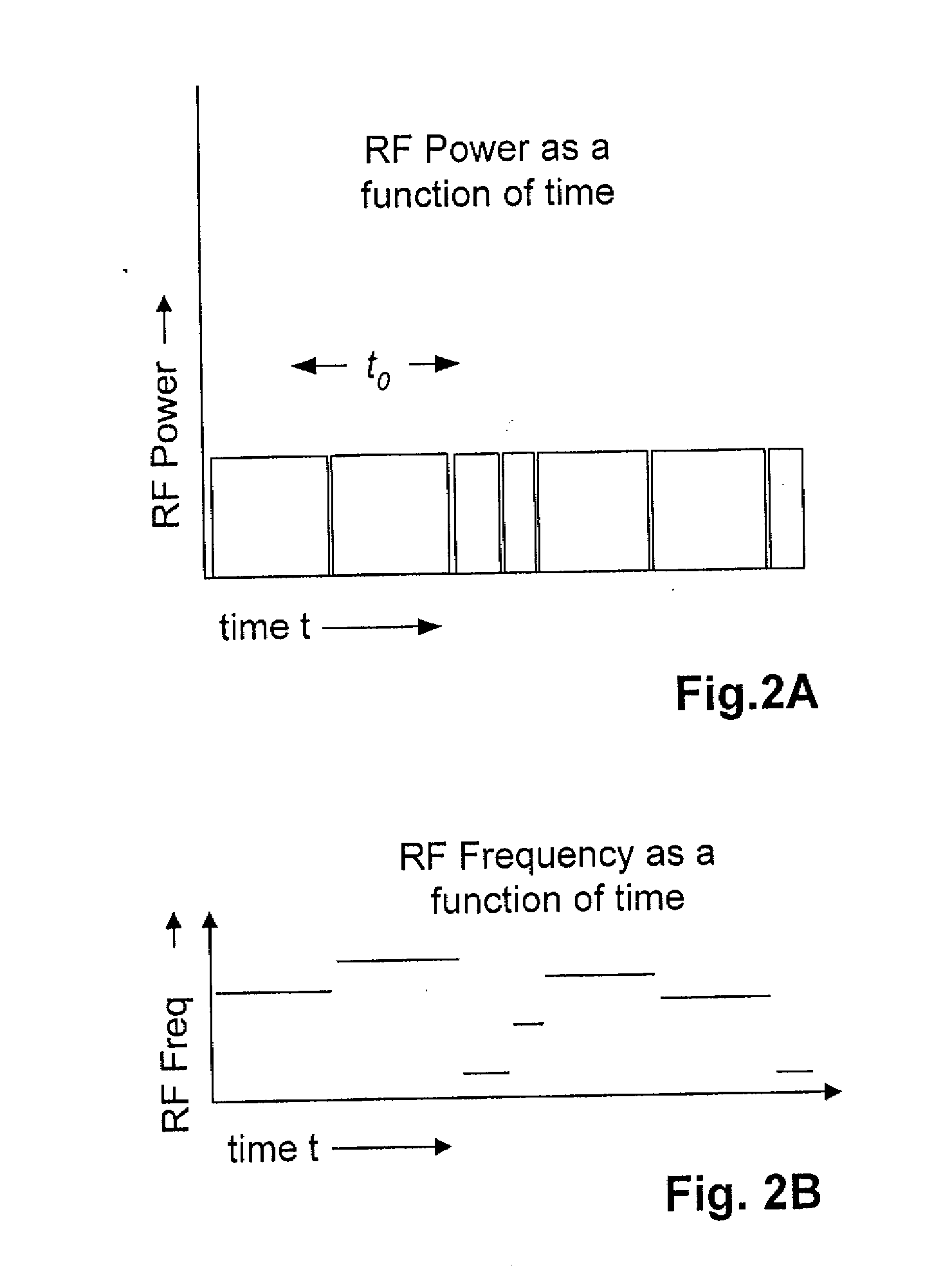
[0024] U.S. Pat. No. 5,828,693 to Mays, et al. issued Oct. 27, 1998 entitled Spread spectrum frequency hopping reader system and U.S. Pat. No. 5,850,181 to Heinrich, et al. issued Dec. 15, 1998 entitled Method of transporting radio frequency power to energize radio frequency identification transponders, assigned to the assignee of the present invention, give details on RFID tags powered by an RF field where the frequency sent to the tags hops from frequency to frequency chosen from a pseudorandomly ordered list of frequencies. In both the above described patents, the RF field is sent out to the tags from a base station as a series of bursts of power at a particular frequency, with the frequency changing for the next burst, but the power and the length of time of the bursts are kept constant. U.S. Pat. No. 5,828,693 teaches that the length of time of each burst the regular series of bursts may be changed to avoid having one or more base stations interfering with one another. Apparatu...


PUM


Abstract

Radio frequency (RF) power is sent out by a base station to radio frequency identification transponders (RFID tags) for a first time at a first frequency. The frequency is changed to a second frequency, and the RF power sent out for a second time substantially different from the fist time so as to tend to improve data throughput. In one embodiment forced frequency “hops” are implemented if the time it takes to perform a particular transaction is greater than the time available on a particular carrier frequency. In one embodiment, a radio frequency identification (RFID) base station processor (in conjunction with program information stored in a base station memory) is adapted to (i) determine the amount of time available on a particular carrier frequency (e.g., pursuant to Federal Communications Commission (FCC) regulations, European Telecommunications Standardization Institute (ETSI) regulations, etc.), (ii) determine the amount of time it would take to perform a particular transaction, and (iii) force the base station to “hop” to another carrier frequency if the transaction time is longer than the available time. In one embodiment, the time it would take to perform a particular transaction is the time it would take to perform the next transaction. In another embodiment, the time it would take to perform a particular transaction is the time it would take to perform the longest (or “worst-case”) transaction. In alternate embodiments, a transaction is defined as the transmission of information (e.g., data, commands, etc.) or both the transmission of information and the reception of related information.

Description

FIELD OF THE INVENTION [0001] The field of the invention is the field of radio frequency (RE) identification (RFID) transponders (tags), and systems for their use. BACKGROUND OF THE INVENTION [0002] RF Transponders (RF Tags) can be used in a multiplicity of ways for locating and identifying accompanying objects and transmitting information about the state of the object. It has been known since the early 60's in U.S. Pat. No. 3,098,971 by R. M. Richardson, that electronic components of transponders could be powered by radio frequency (RF) electromagnetic (EM) waves sent by a “base station” and received by a tag antenna on the transponder. The RF EM field induces an alternating current in the transponder antenna which can be rectified by an RF diode on the transponder, and the rectified current can be used for a power supply for the electronic components of the transponder. The transponder antenna loading is changed by something that was to be measured, for example a microphone resist...

Claims


Application Information

Patent Timeline
Patent Type & Authority Applications(United States)
IPC IPC(8): H04Q5/22
CPCG06K7/0008
Inventor PILLAI, VIJAYMARTINEZ, RENE D.RAMAMURTHY, SHASHIEASTBURN, DAVID LEE
Owner PILLAI VIJAY
Why Eureka
Try Eureka