

Children's dental mirror
a technology for children and mirrors, applied in shaving accessories, lighting elements, lighting and heating devices, etc., can solve the problems of harmful acid, tooth decay, abscesses, and causing tremendous pain
- Summary
- Abstract
- Description
- Claims
- Application Information
AI Technical Summary
Benefits of technology
Problems solved by technology
Method used
Image

Examples
Embodiment Construction
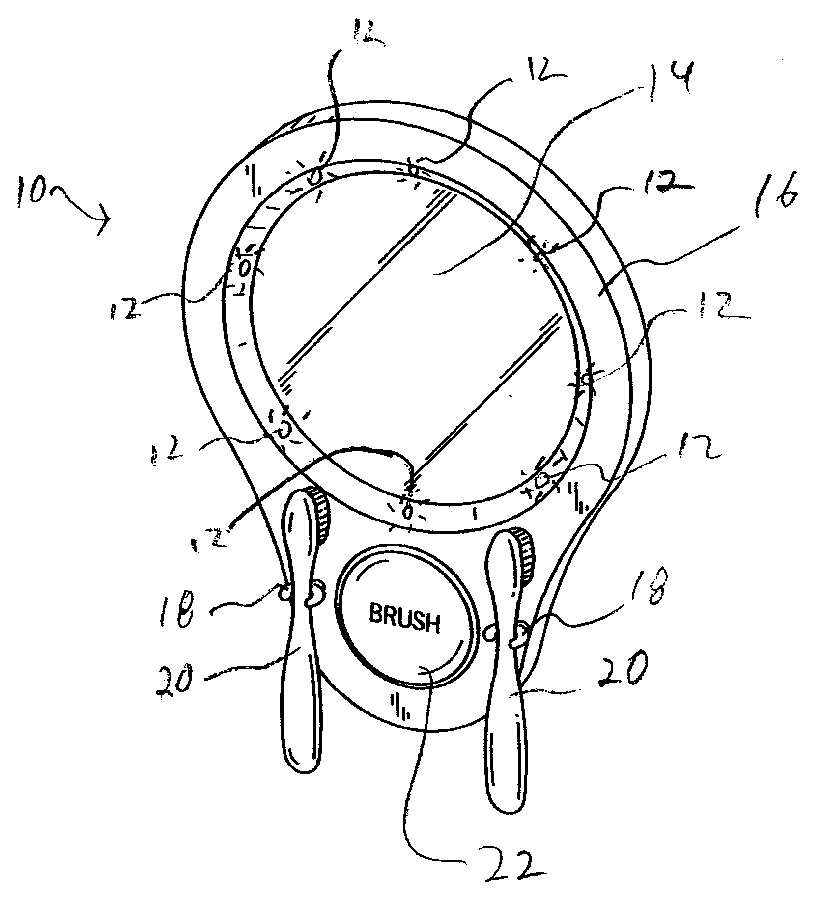
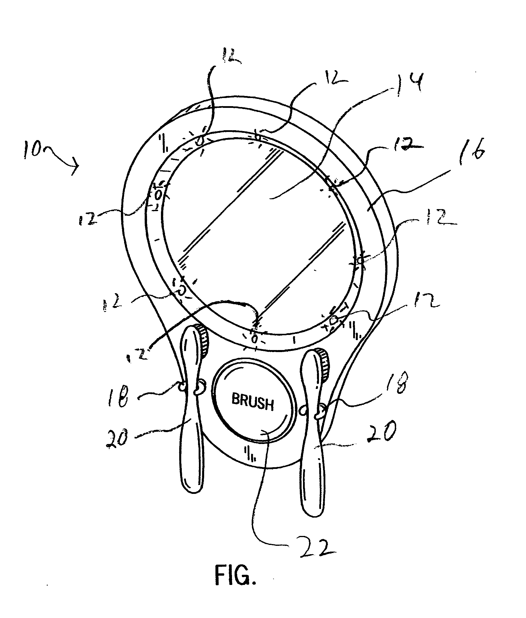
[0013] The FIGURE shows a children's dental mirror 10 in accordance with the principles of the present invention. A children's dental mirror 10 of the present invention incorporates a timer integrated with it. In one embodiment, the timer is between about two and about three minutes. In one embodiment, the timer is about two minutes. A children's dental mirror 10 of the present invention provides children a station to provide feedback and entertainment while brushing their teeth. The children's dental mirror can also have lights 12 around the circumference of a mirror 14 that can pulsate to the timer. In one embodiment, in addition to the pulsating lights the device can provide an audio sound byte during the brushing period. The timer can have several audio sound bytes and be changed by a sliding switch. The timer, lights, and sound can be power by battery. Thus, a children's dental mirror 10 of the present invention offers children an interaction device with a selection of audio so...
PUM
 Abstract
Description
Claims
Application Information