Measuring apparatus, measuring method, and sound signal processing apparatus

a technology of measuring apparatus and measuring method, applied in the direction of electrical apparatus, stereophonic system, stereophonic arrangment, etc., can solve the problems of limited delay time length, inability to measure delay time related to the relatively long distance between the speaker and the microphone, etc., and achieve the effect of simple operation and measurement of long delay tim

Inactive Publication Date: 2007-04-19
SONY CORP
View PDF4 Cites 6 Cited by
  • Summary
  • Abstract
  • Description
  • Claims
  • Application Information

AI Technical Summary

Benefits of technology

[0030] As described above, according to the embodiments of the invention, it is possible to measure long delay time without being limited to a frequency of a sine wave signal output from the speaker. That is, from the point of view described above, the delay time can be measured without being limited to the type of a speaker that is used.
[0031] Furthermore, in order to realize the above-described delay time measurement according to the embodiments of the invention, a process of mixing sine wave signals is needed unlike in the method used in the related art. However, as for the mixing process, it is sufficient to perform a relatively simple operation based on equation using trigonometric function. Other than the mixing process, the delay time

Problems solved by technology

However, selecting the frequency of a used sine wave signal depending on the distance between the speaker and the microphone, which are objects to be measured, means that measurable delay time length may be limited to a frequency band that can be

Method used


Image

  • Measuring apparatus, measuring method, and sound signal processing apparatus
  • Measuring apparatus, measuring method, and sound signal processing apparatus
  • Measuring apparatus, measuring method, and sound signal processing apparatus

Examples


first embodiment

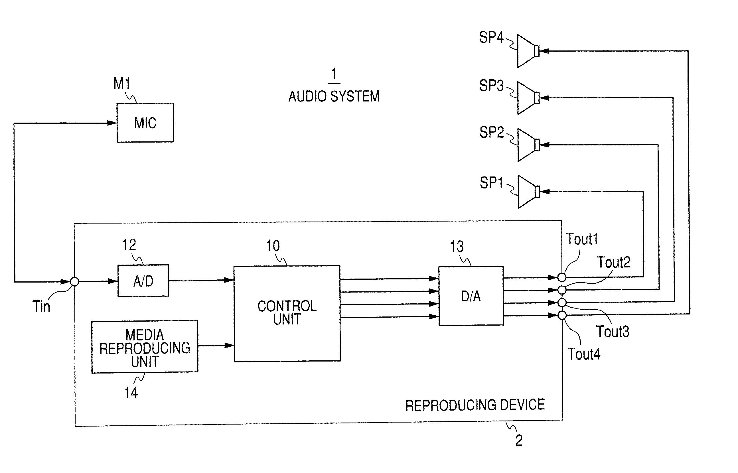
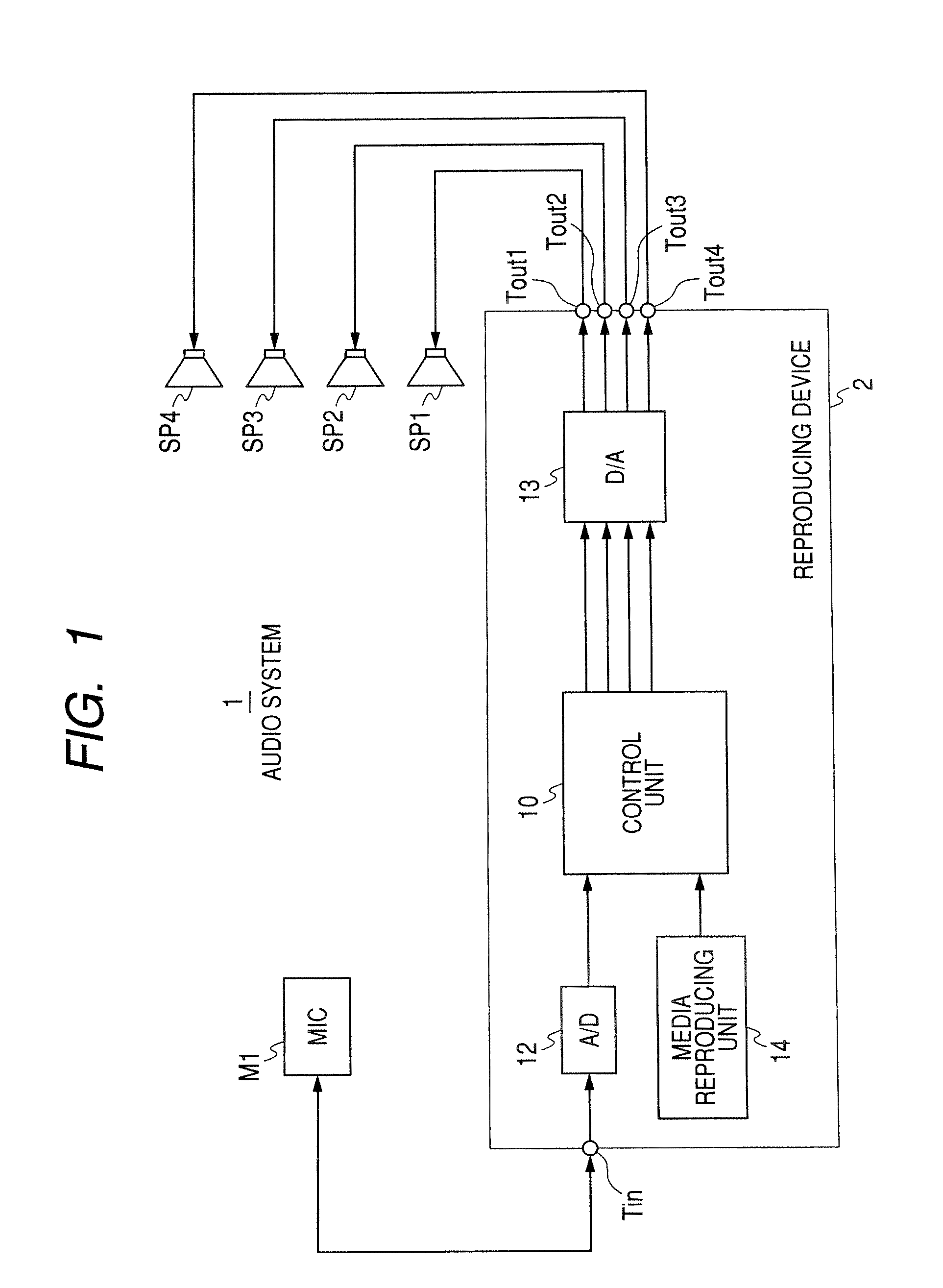
[0082]FIG. 3 is a view schematically explaining an operation of measuring delay time according to a first embodiment. Here, in the following description, only an operation of measuring delay time with respect to one speaker SP will be described for the convenience of explanation. However, in order to measure delay time with respect to the respective speakers SP, the same measuring operation may be repeatedly performed for the respective speakers SP.

[0083] First, in the first embodiment, an A signal (first sine wave signal) having a frequency of 320 Hz and a B signal (second sine wave signal) having a frequency of 300 Hz are set as sine wave signals having different frequencies. In addition, the A and B signals are sequentially output from the speaker SP, and collected signals corresponding to the sequentially output A and B signals are sequentially input.

[0084] That is, in this case, as shown by 1> in FIG. 3, for example, the A signal is output from the speaker SP. Then, a signal,...

second embodiment

[0127]FIG. 9 is a view schematically illustrating an operation of measuring delay time according to a second embodiment.

[0128] In the second embodiment, A and B signals are set to be output at the same time, as compared with the first embodiment in which the A and B signals are separately output.

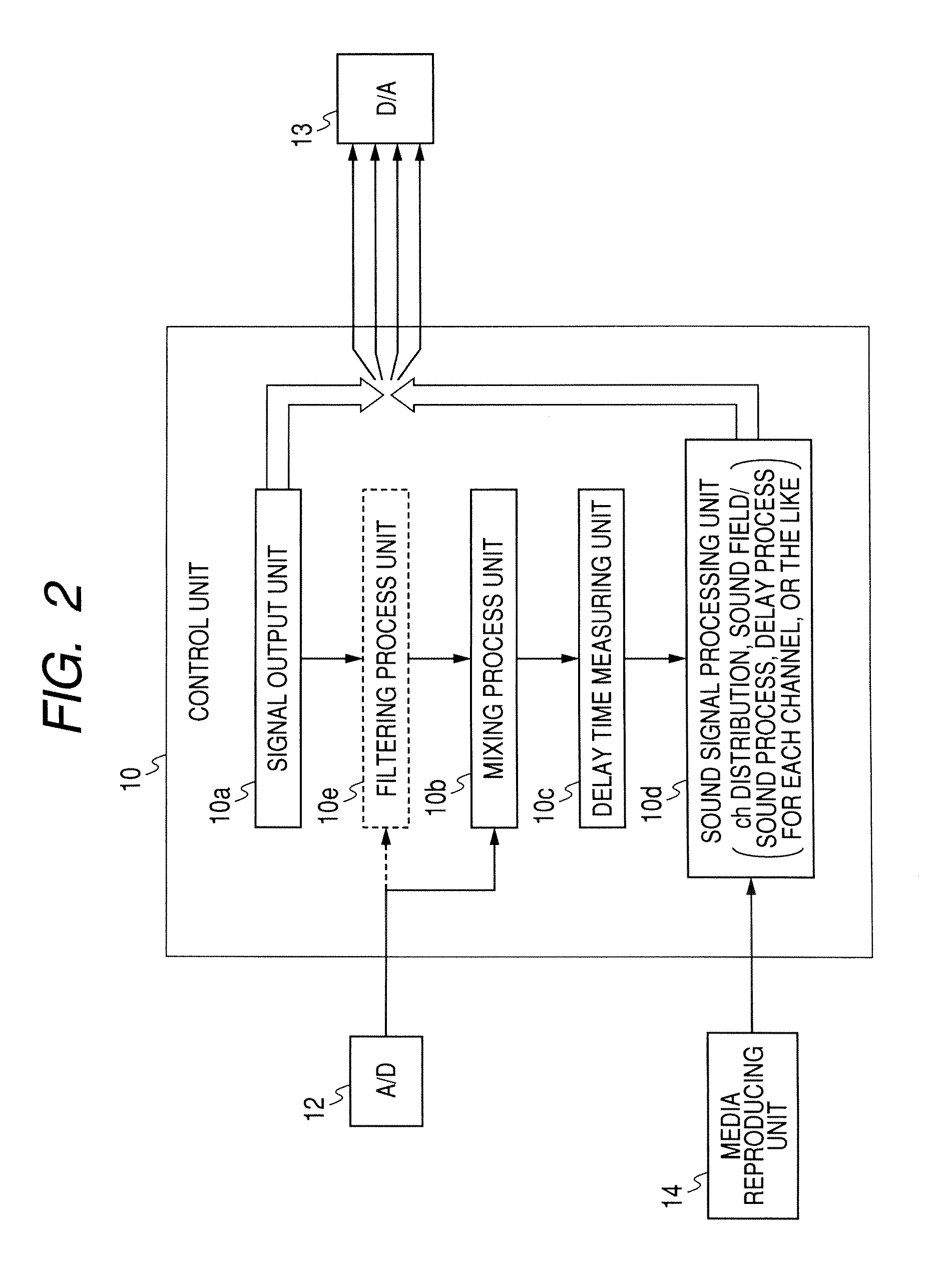
[0129] Here, in order to perform a mixing process, these A and B signals need to be acquired as separate signals. Therefore, in the second embodiment, a band pass filter, which is provided to separately output the A and B signals that are output at the same time such that the A and B signals can be acquired as separate signals, is needed. That is, in this case, the control unit 10 includes the filtering process unit 10e described above.

[0130] Hereinafter, the operation according to the second embodiment will be specifically described. First, as shown by 1>in FIG. 9, the A and B signals are output at the same time. For example, the simultaneous output is made by outputting a signal, which ...


PUM


Abstract

A measuring apparatus that measures sound arrival delay time from a speaker to a microphone on the basis of a result obtained by collecting signals output from the speaker by means of the microphone includes: measuring means for measuring the sound arrival delay time that makes a control such that a first sine wave signal having a first frequency and a second sine wave signal having a second frequency different from the first frequency are output from the speaker, is input with the first sine wave signal and the second sine wave signal collected by the microphone and then mixes the first sine wave signal and the second sine wave signal so as to generate a third sine wave signal having a frequency corresponding to a difference between the first frequency and the second frequency, and measures the sound arrival delay time on the basis of the third sine wave signal.

Description

CROSS REFERENCES TO RELATED APPLICATIONS [0001] The present invention contains subject matter related to Japanese Patent Application JP 2005-304760 filed in the Japanese Patent Office on Oct. 19, 2005, the entire contents of which being incorporated herein by reference.BACKGROUND OF THE INVENTION [0002] 1. Field of the Invention [0003] The present invention relates to measuring apparatus and method of measuring sound arrival delay time from a speaker to a microphone on the basis of a result obtained by collecting a signal output from the speaker by means of the microphone. In addition, the invention relates to a sound signal processing apparatus having a function of measuring the sound arrival delay time. [0004] 2. Description of the Related Art [0005] In the related art, particularly in an audio system that outputs audio signals through multi-channels, a method has been known in which a test signal, such as a sine wave signal or a TSP (time stretched pulse) signal, is output from a...

Claims


Application Information

Patent Timeline
IPC IPC(8): H04R29/00
CPCH04R2499/13H04S7/301H04S7/305
Inventor KINO, YASUYUKI
Owner SONY CORP
Why Eureka
Try Eureka