Front end for 3D imaging camera

Inactive Publication Date: 2007-04-19
3M INNOVATIVE PROPERTIES CO
View PDF24 Cites 64 Cited by
  • Summary
  • Abstract
  • Description
  • Claims
  • Application Information

AI Technical Summary

Benefits of technology

[0007] The above summary of the present invention is not intended to describe each illustrated embodiment or every implementation of the present invention. The figures and the detailed description which follow more particularly exemplify these embodiments.

Problems solved by technology

The current front ends for dental 3D cameras include expensive precision optical items and, therefore, tend not to be disposable, which means that the dentist must sterilize the front end between uses with different patients.

Method used


Image

  • Front end for 3D imaging camera
  • Front end for 3D imaging camera
  • Front end for 3D imaging camera

Examples


Embodiment Construction

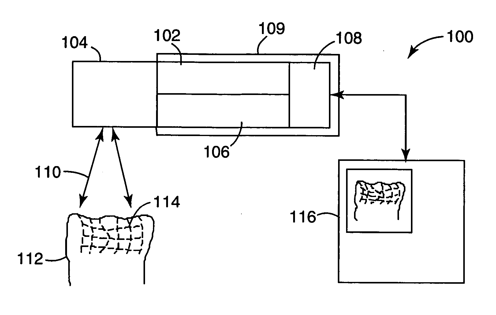
[0016] The present invention is applicable to three-dimensional (3D) imaging systems, and is more particularly applicable to 3D imaging systems used in dentistry and other medical applications. The imaging system may be able to produce a 3D virtual image of a tooth or teeth in the patient's mouth. After several images have been taken, a processor may be able to “stitch together” a plurality of images so as to form a virtual 3D model of part, or all, of the patient's mouth.

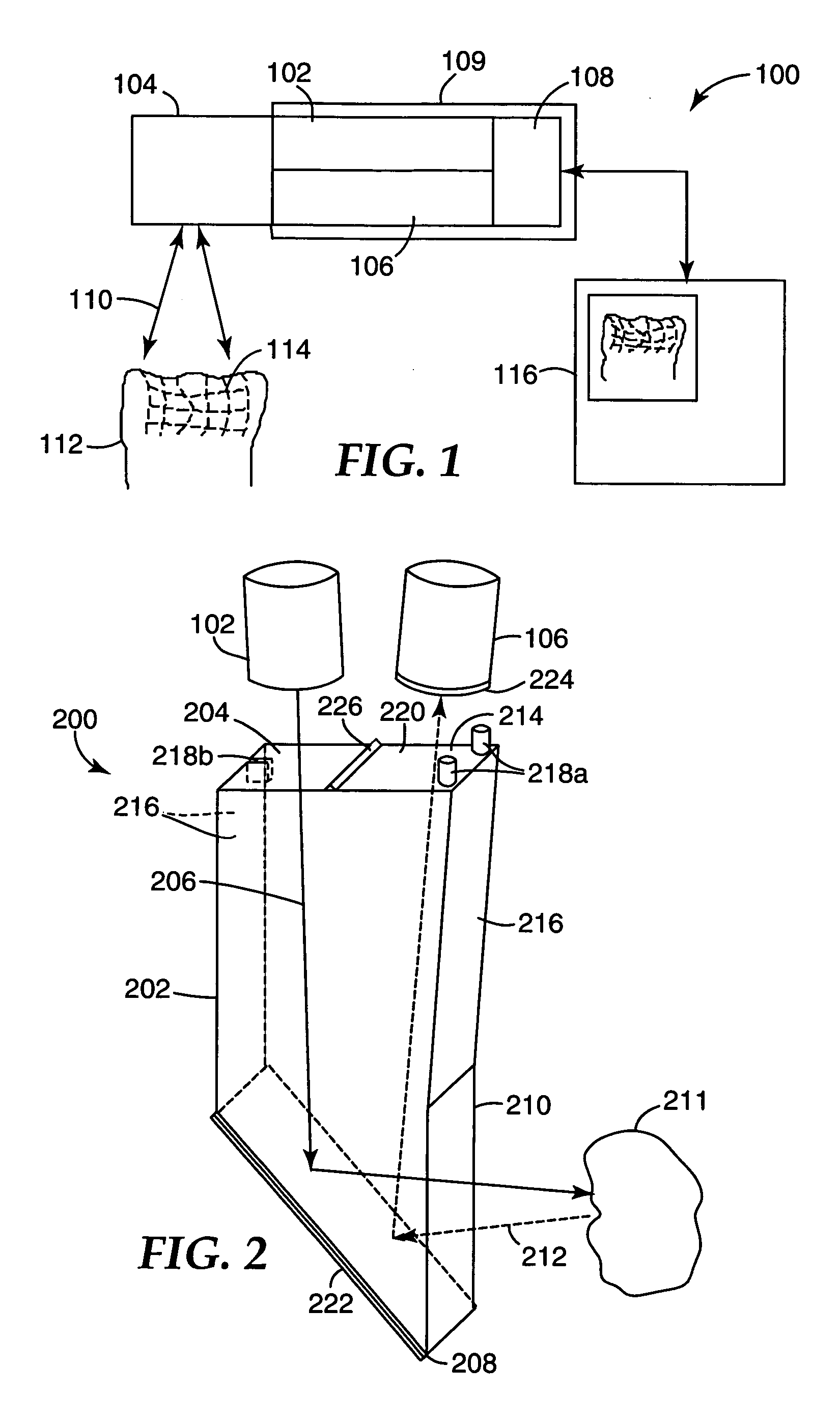
[0017] An exemplary embodiment of a 3D imaging system 100 that may be used for taking 3D images of a patient's tooth or teeth is schematically illustrated in FIG. 1. The system 100 includes a projection unit 102, an optical transceiver unit 104, a detection unit 106 and a control unit 108. The projection unit 102, detection unit 106 and control unit 108 may be housed within a housing 109. The optical transceiver unit may be wholly or partially located within the housing 109.

[0018] The projection unit 102 produces...


PUM


Abstract

A three-dimensional imaging system for forming a three dimensional image of an object tooth includes a projection unit capable of generating a projected light pattern and a detector unit capable of detecting an image pattern received from the object tooth. An optical transceiver unit transmits the projected pattern generated by the projection unit to the object tooth and receives the image pattern from the object tooth. The optical transceiver is formed of an integrated body having at least first and second transmitting faces and a reflecting surface that reflects light propagating within the body. In some embodiments, the projected pattern light is polarized in one polarization state and the detected image light is polarized in a second polarization state orthogonal to the first polarization state.

Description

FIELD OF THE INVENTION [0001] The present invention relates to cameras that detect a three-dimensional image, and more particularly to the front end of a three-dimensional camera for dental and medical use. BACKGROUND [0002] Cameras have been used in dentistry for a number of years. Initially, two-dimensional cameras were used for providing an image to the dentist and patient on a monitor. The image was used primarily for inspection purposes. More recently, three-dimensional (3D) cameras have been introduced for extracting 3D data for a tooth or of several teeth. The 3D data are used to produce a virtual 3D image of the patient's tooth or teeth. This virtual image may be used for manufacturing replacement teeth, or partial replacements, for example as might be used in a prosthesis such as a bridge or a crown. The 3D map of the patient's teeth may be also be used as a basis for making orthodontic braces. The 3D image can be used to replace the need for making a mold of the patient's ...

Claims


Application Information

Patent Timeline
Patent Type & Authority Applications(United States)
IPC IPC(8): G03B29/00A61B1/04
CPCG03B35/10A61C9/006A61B1/00009A61B1/00193A61B1/247A61B5/1079A61B5/4547A61B1/00194A61B1/0605
Inventor O'KEEFE, MICHAEL W.GRACE, JENNIFER L.
Owner 3M INNOVATIVE PROPERTIES CO
Why Eureka
Try Eureka