Injection unit, and method for the adjustment thereof

a technology of injection unit and injection mold, which is applied in the field of injection unit and method for the adjustment thereof, can solve the problems of obstructing the weight accuracy of injection molded parts, obstructing the cleaning of applicable machine parts, and reducing the accuracy of injection molding parts,

Inactive Publication Date: 2007-04-19
NETABTAL MASCHEN
View PDF10 Cites 18 Cited by
  • Summary
  • Abstract
  • Description
  • Claims
  • Application Information

AI Technical Summary

Benefits of technology

[0046]FIG. 4 is an enlarged section and shows, as an alternative to FIG. 3, a compact version of the guide shoes. As shown in FIG. 4, in the operating state, there is an approximate equilibrium between the ma...

Problems solved by technology

The emergence of melt is detrimental with respect to the cleaning of the applicable machine parts.
But a far more serious drawback lies in the obstructive effect with regard to the weight accuracy of the injection molded parts, because an uncontrollable amount [of melt] is lost in the transfer zone, even when the dosing of melt is as accurate as possible.
However, more recent measurements have shown that when the pressing force is too high, the die to which the pressure is being applied is mechanically deformed, especially during the phase in which a corresponding melt pressure does not yet prevail.
In addition to possible damage to the mold, this can also compromise the quality of the injection molded parts.
The major drawback of solutions based on EP 9 422 224 lies in the eccentric generation of the pressing force.
What remains unresolved, however, are the uncontrollable forces that develop, be it from inaccuracies in the structure of an inadequate centering of the plasticizing cylinder tip and the mold injection port or from the eccentricity of th...

Method used


Image

  • Injection unit, and method for the adjustment thereof
  • Injection unit, and method for the adjustment thereof
  • Injection unit, and method for the adjustment thereof

Examples


Embodiment Construction

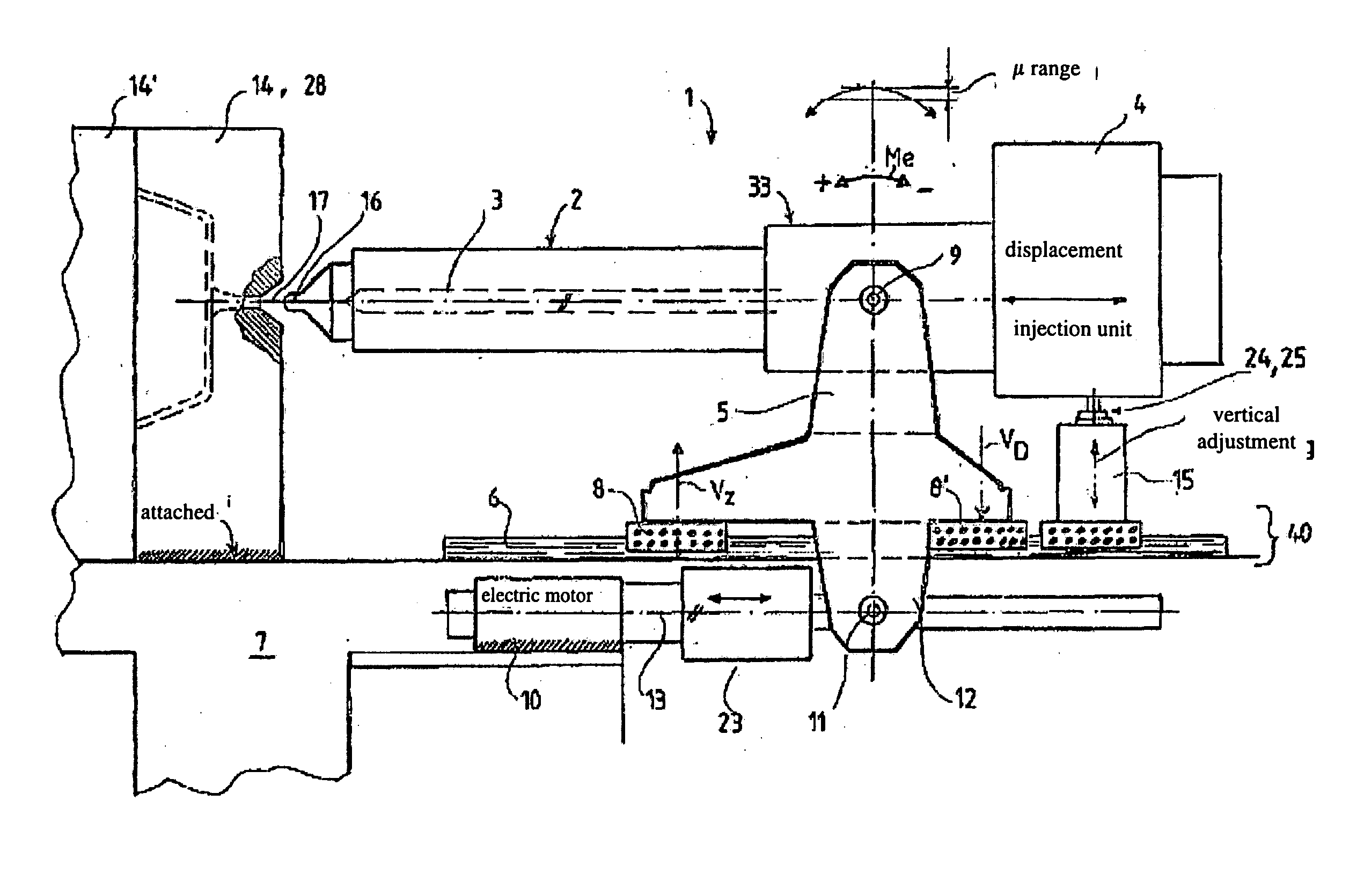
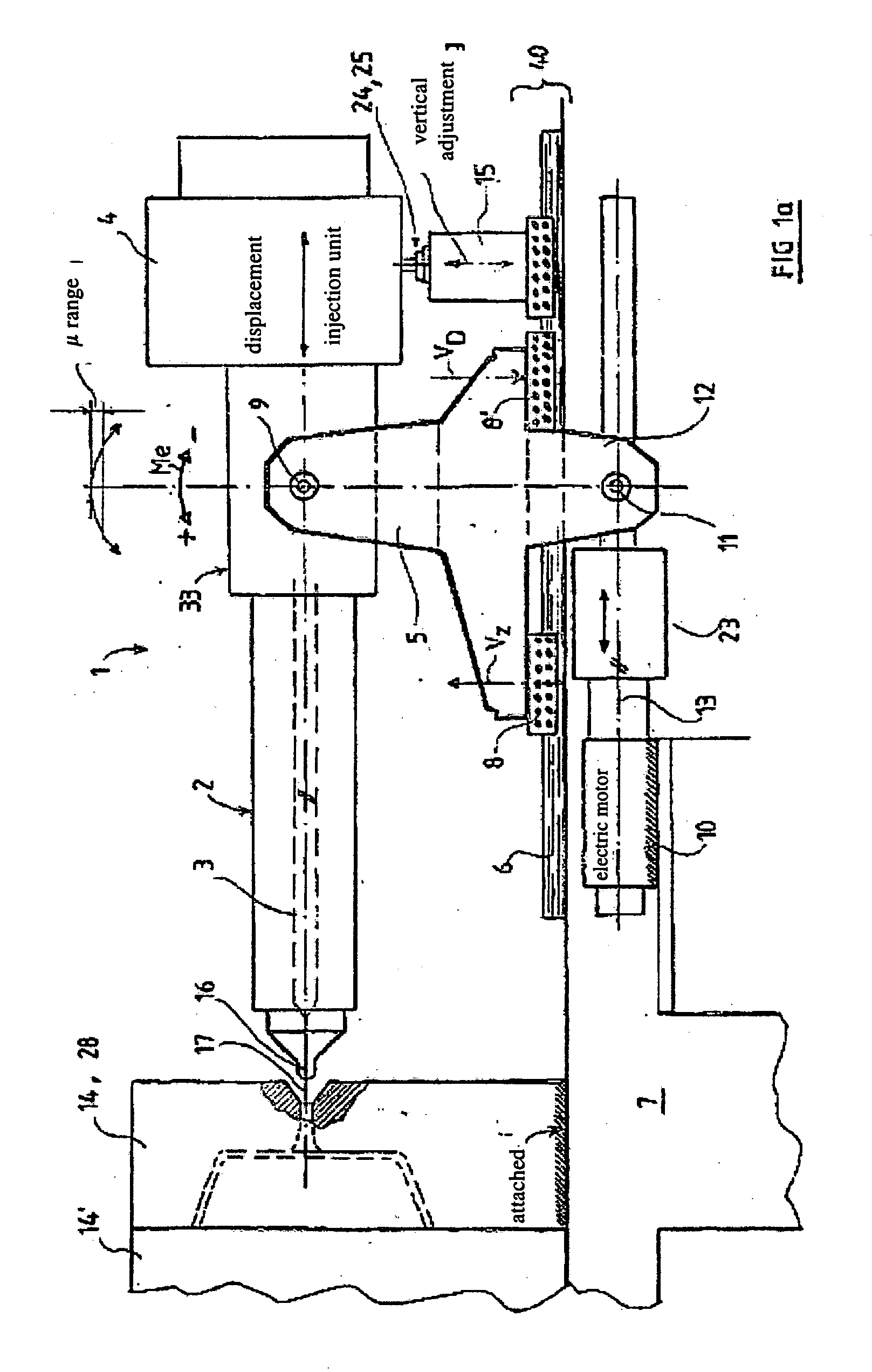
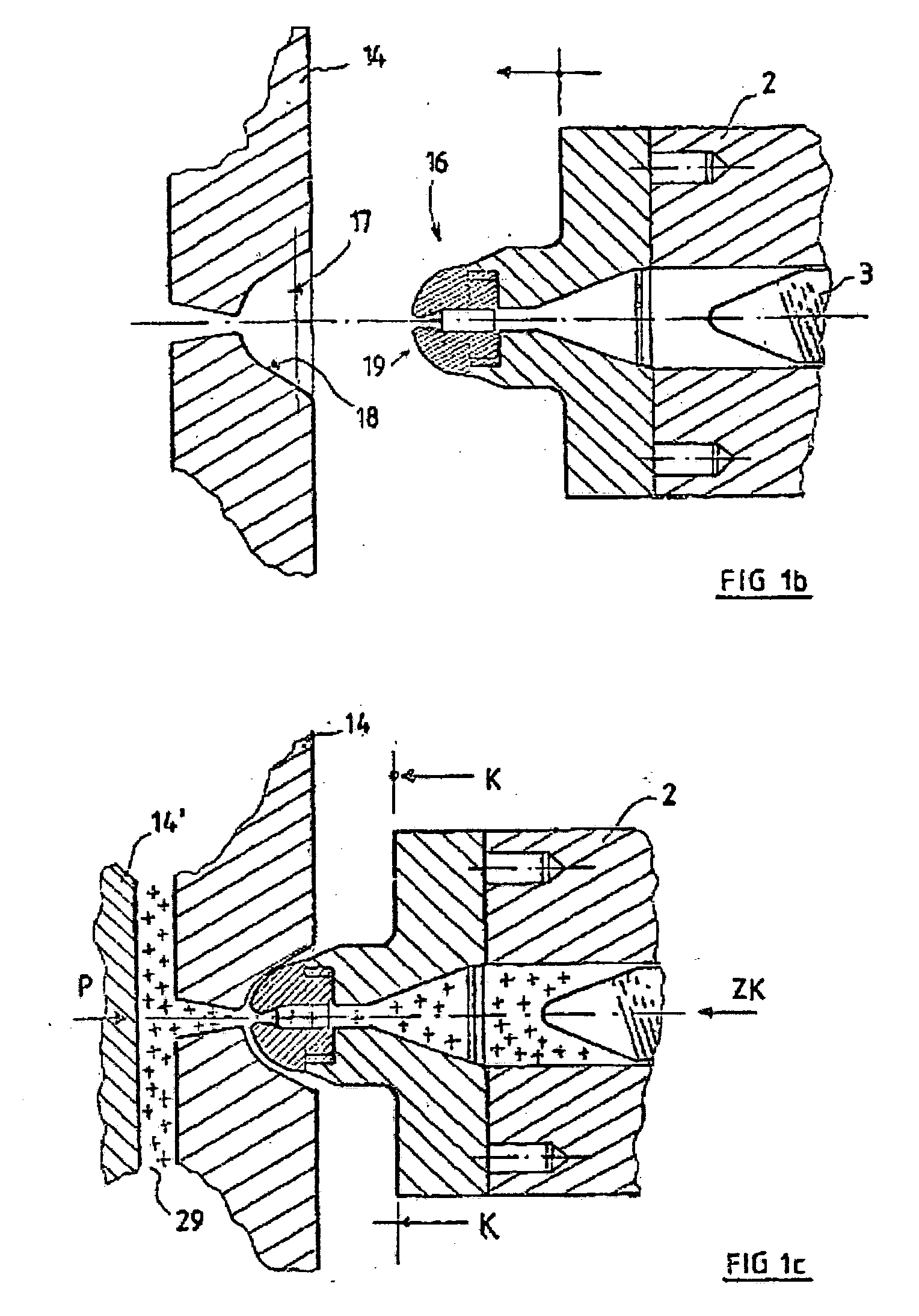
[0014] The inventive solution is characterized by the fact that the injection unit is supported by a support which is moveable on runners of the injection molding machine's frame and comprises a drive unit for pressing the plasticizing cylinder to the injection mold while achieving a concentric sealing connection.

[0015] Surprisingly, with the new invention all key advantages of the solutions of the prior art can be integrated into an injection unit and, additionally, an optimal sealing connection can be achieved, without the disadvantages specifically described in each case.

The support simultaneously performs the support and displacement functions. This makes it possible to utilize the advantages of EP 0 422 224 with regard to access to the plasticizing cylinder.

The injection worm is completely exposed, permitting unobstructed access for all necessary work, especially cleaning work, as well as unobstructed visual inspection.

What is decisive, however, is the fact that there is...


PUM

PropertyMeasurementUnit
Stress optical coefficientaaaaaaaaaa
Deformation enthalpyaaaaaaaaaa

Abstract

The invention relates to a method and an injection unit which is movable on runners (6) of the frame (7) of an injection molding machine with the aid of a running gear (40) and comprises a drive unit (10, 23) for axially displacing and pressing the plasticizing cylinder (2) to the injection mold. According to the invention, the tip (16) of the plasticizing cylinder (16) is adjusted on both a vertical and a horizontal plane via a slight rotary movement of the entire injection unit (1) prior to the production if the concentric sealing connection to the injection port (17) of the mold is insufficient. The inventive injection unit (1) is supported via a support (5) that is disposed so as to be movable on the frame (7) of the injection-molded part while being provided with an individual drive unit (10, 23) via which the plasticizing cylinder (2) can be pressed to the injection mold so as to create a concentric sealing connection thereto.

Description

TECHNICAL DOMAIN [0001] The invention relates to an injection unit which is moveable on runners of the frame of an injection molding machine with the aid of a running gear and comprises a drive unit for axially displacing and pressing the plasticizing cylinder to the injection mold. PRIOR ART [0002] Besides the actual molds and the locking mechanism for the molds, the injection unit of an injecting molding machine is one of the main subassemblies of an injection molding machine. The central function of the injection unit lies in the processing of the plastic melt, the metered delivery of the melt into the cavities of the injection mold and the buildup and maintenance of the required pressure for the injection-molded parts until they solidify. [0003] In practice, there are several known possibilities for transferring the melt from the plasticizing cylinder into the mold. If the plasticizing cylinder has a nozzle seal, the individual phases of injection can be defined within clear lim...

Claims


Application Information

Patent Timeline
IPC IPC(8): B29C45/46B29C45/07B29C45/17
CPCB29C45/07B29C45/1761B29C45/1777B29C45/1781
Inventor WEINMANN, ROBERT
Owner NETABTAL MASCHEN
Why Eureka
Try Eureka