Ostomy coupling

a technology of ostomy and coupling, which is applied in the field of ostomy couplings, can solve the problems of difficult re-form into the original operative shape, difficult to empty or clean, and the disposable ostomy appliance unit may simply not be designed to be used, so as to prevent the re-use of the disposable unit

Active Publication Date: 2007-04-19
CONVATEC TECH INC
View PDF17 Cites 94 Cited by
  • Summary
  • Abstract
  • Description
  • Claims
  • Application Information

AI Technical Summary

Benefits of technology

[0006] In one form, the ostomy appliance comprises a body-side mounting unit to be worn on the body, and a disposable ostomy appliance unit attachable thereto. The body-side unit is intended for use more than once, whereas the disposable unit is intended for only single use. One of the coupling elements is carried by the body-side unit, and the other coupling element is carried by the disposable unit. The invention is used to prevent the appliance-side coupling element from being re-fastened securely to the body-side coupling element after first use, thereby to prevent re-use of the disposable unit. Configuring the coupling element of the appliance side to be rendered inoperative still permits the body-side coupling element to be used with a replacement disposable unit, without having to changing the body-side coupling element worn on the body.

Problems solved by technology

Certain disposable ostomy appliance units with a collection chamber without a drainage outlet, and / or a collection chamber that includes tight folds, may be difficult to empty or clean, or may be difficult to re-form into an original operative shape.
Other disposable ostomy appliance units may simply not be designed to be used more than once, whether for hygiene reasons, or other reasons.
It may be inadvisable to try to re-use the device after a first time that the device is removed, for example, if the seal may be contaminated by stomal discharge.

Method used


Image

  • Ostomy coupling
  • Ostomy coupling
  • Ostomy coupling

Examples


first embodiment

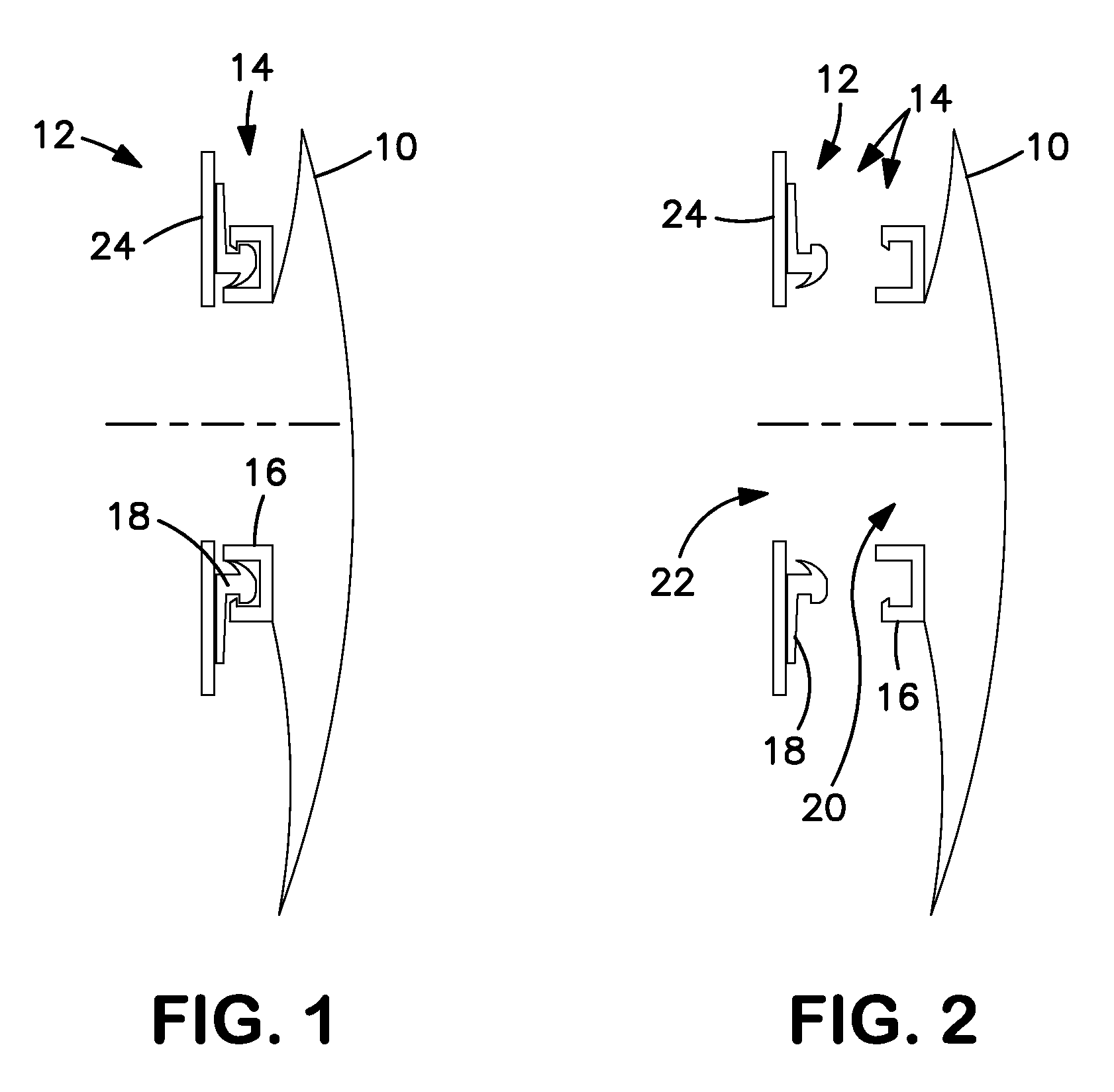
[0035] Referring to FIGS. 1 and 2, an ostomy appliance comprises a disposable unit in the form of a collection pouch 10, and a re-usable unit in the form of a body-side mounting unit 12. The collection pouch 10 may be of a type that is intended for use only once, after which the pouch 10 is intended for disposal. The body-side mounting unit 12 is intended to remain on the body, and be used multiple times to permit replacement pouches 10 to be fitted and removed without having to remove the body-side mounting unit 12 from the body.

[0036] The collection pouch 10 is releasably fastened to the body-side mounting unit 12 by means of an ostomy coupling 14. The ostomy coupling 14 includes confronting first and second coupling members 16 and 18. The first (“non-body-side” or “pouch-side”) coupling member 16 includes a first stomal orifice 20, and is carried by the pouch 10 at a pouch entrance aperture. The second (“body-side”) coupling member 18 includes a second stomal orifice 22, and is c...

second embodiment

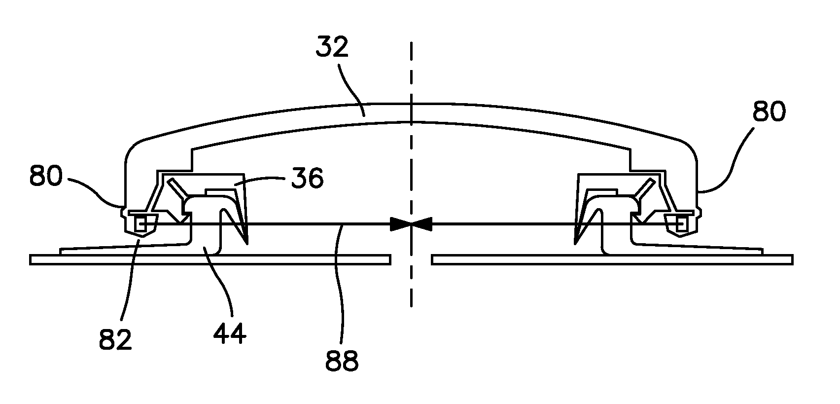
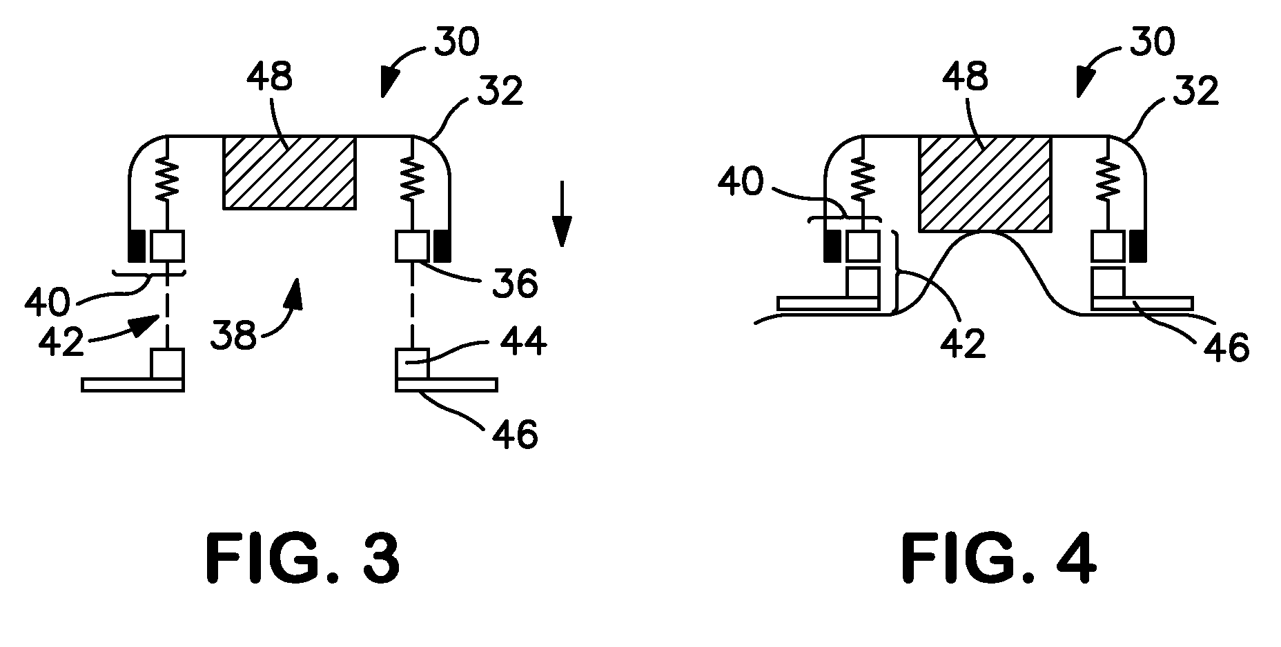
[0039] Referring to FIGS. 3-6, in a second embodiment, an ostomy appliance comprises a controlled discharge device 30. The controlled discharge device generally comprises a cap 32, a collection chamber in the form of a tube 34, and mounting ring 36. The tube 34 is collapsible, for example, in a bellows-like form. The mounting ring 36 comprises a stomal aperture 38. The cap 32, tube 34 and the mounting ring 36 are integrally molded or otherwise permanently joined to each other to form a unitary item.

[0040] The device 30 comprises two ostomy couplings 40 and 42. The first coupling 40 is formed between the cap 32 (acting as a first coupling member) and the mounting ring 36 (acting as a second coupling member). The first coupling 40 serves to fasten the cap 32 to the mounting ring 36 in an initial state of the device 30, as shown in FIG. 3. In the initial state, the tube 34 is collapsed substantially to a flat bellows form, and the cap 32 is held directly adjacent the mounting ring 36 a...


PUM


Abstract

A single-use ostomy appliance is described including an ostomy coupling for releasable coupling first and second portions at a stomal orifice. The two portions may be separable body-side and non-body-side parts, or the two portions may be portions of a unitary ostomy device such as a controlled evacuation device. The coupling includes a mechanical fastener configured such that the coupling is rendered substantially not resecurable after the fastener is released.

Description

FIELD OF THE INVENTION [0001] The present invention relates to the field of ostomy couplings. It more particularly relates to releasably securing together a body-side coupling element and an appliance-side coupling element of an ostomy appliance at or around a stomal orifice. The ostomy appliance may include for example, a collection pouch, a stoma port (or plug or cap), or a controlled evacuation device. BACKGROUND TO THE INVENTION [0002] The majority of conventional ostomy couplings are either of the mechanical fastening type, or the adhesive fastening type. A mechanical interference fastening type may be especially suitable where the advantage of a secure and positive mechanical fastening is desired. [0003] Conventional ostomy couplings using a mechanical interference fastening generally comprise at least two coupling elements, one of which may, for example, be a body-side coupling element for adhesive attachment to the body. The other coupling element may, for example, be a non-...

Claims


Application Information

Patent Timeline
Patent Type & Authority Applications(United States)
IPC IPC(8): A61F5/44
CPCA61F5/445A61F5/448A61F2005/4402A61F2005/4486
Inventor CLINE, JOHNBLUM, JOHN L.STACEY, GARYDAVIES, PHILLIPBECKETT, TREVOR
Owner CONVATEC TECH INC
Why Eureka
Try Eureka