
Lancet block and lancet activating device

a technology of lancet and activation device, which is applied in the field of needle for micro blood sampling, can solve the problems of user's finger being pricked with the tip of the needle inadvertently, and the worker who disposes of discarded lancets is also exposed to so as to avoid a risk of injury, prevent bacterial infection, and simplify the manufacturing process

Inactive Publication Date: 2011-02-17
MITI SYST
View PDF5 Cites 21 Cited by
  • Summary
  • Abstract
  • Description
  • Claims
  • Application Information

AI Technical Summary

Benefits of technology

[0011]Another object of the present invention is to provide a lancet block and a lancet activating device, in which an ejected needle tip of a lancet can be prevented from being exposed externally so as to reduce a risk of injury by the needle tip.
[0012]Yet another object of the present invention is to provide to a lancet block and a lancet activating device, in which a used lancet can be automatically ejected so as to prevent a user from re-using the used lancet.
[0013]Still another object of the present invention is to provide a lancet block which is deformed to prevent the lancet from being re-mounted during the use / ejection of the lancet, so that the re-use of the lancet can be prevented, and a lancet activating device.
[0020]The lancet-receiving member includes an upper portion and a lower portion extending by a predetermined length from a lower distal end thereof, the lower portion having an outer diameter smaller than that of the upper portion. The lancet-receiving member includes a lancet block movement passageway penetratingly formed longitudinally therein so that one or more lancet blocks can be fittingly inserted into the lancet block movement passageway in the longitudinal direction so as to be vertically and longitudinally moved but restricted in their rotation along the lancet block movement passageway and a cam projection exposure slot opening formed longitudinally on the periphery of the lower portion of the lancet-receiving member so as to allow a cam projection of a lancet block to be exposed externally therethrough. The lancet-receiving member is fittingly inserted into the rotation drive unit in such a fashion that an outer periphery of the lancet-receiving member comes into close contact with an inner periphery of the rotation drive unit so that the lancet-receiving member can rotate relatively with respect to the rotation drive unit within the rotation drive unit, and is fixedly coupled to the housing.
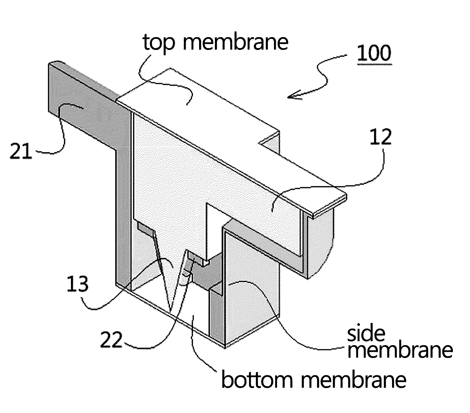
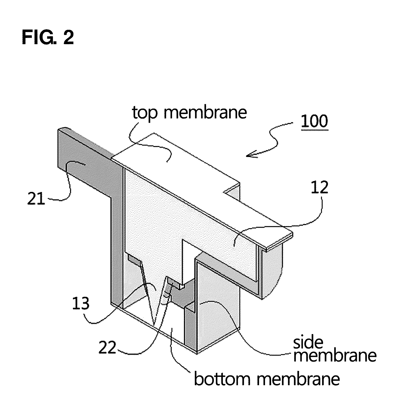
[0025]In addition, according to the present invention, when a lancet is mounted within the lancet activating device or after the lancet is used, a tip of the needle 13 of the lancet is prevented from being exposed externally, thereby avoiding a risk of any injury by the needle tip and preventing bacterial infection due to such injury.
[0026]Besides, according to the present invention, a tip of the lancet needle is formed of a polymeric material so that the manufacturing process is simplified, thereby reducing the manufacturing cost.

Problems solved by technology

However, since the lancet must be replaced with new one each time after use, its use is complicated.
Also, upon the replacement of the used lancet, a needle of the lancet is exposed outwardly from an opening of the lancet, and thus a user's finger may be pricked with a tip of the needle inadvertently.
In addition, a worker who disposes of discarded lancets is also exposed to a risk of injury.
However, such a lancet activating device entails a problem in that since a needle tip of the ejected lancet is not protected, there is a risk of injury by the needle tip.
However, such conventional lancets and lancet activating devices involve drawbacks in that they are complicated in their constructions, which leads to an increase in the manufacturing cost, thereby decreasing economic efficiency, and in that a work of mounting a new lancet is complex, thereby deteriorating convenience of use.

Method used


Image

  • Lancet block and lancet activating device
  • Lancet block and lancet activating device
  • Lancet block and lancet activating device

Examples


Embodiment Construction

[0043]Hereinafter, the present invention will be described in detail in connection with the preferred embodiments with reference to the accompanying drawings. However, these embodiments are for illustrative purposes, and the scope of the present invention is not limited thereto. Also, it will be understood by those skilled in the art that various modifications and variations can be made to the present invention without departing from the spirit and scope of the appended claims based on the illustrative embodiments.

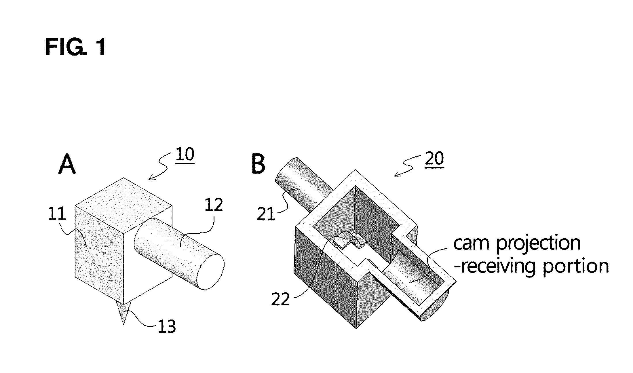
[0044]In the drawings, although it has been shown that a lancet body 11, a lancet housing 20 and a lancet block 100 are formed in a cubic shape, this is merely illustrative and they may be formed in other shapes (e.g., a cylindrical shape).

[0045]FIG. 1 is a perspective view illustrating examples of a lancet (A) and a lancet housing (B) according to the present invention, and FIG. 2 is a cross-sectional perspective view illustrating an example of a lancet block 100 in which...


PUM


Abstract

A lancet block comprises a lancet comprising a cam projection and a lancet housing receiving the lancet in such a fashion that the lancet can be vertically moved relatively with respect to the lancet housing. A top wall of the lancet housing and a side wall of the lancet housing corresponding to the cam projection of the lancet are formed of a thin membrane made of a material capable of being easily disrupted and a bottom wall of the lancet housing is formed of a thin membrane made of a material capable of being easily disrupted by a tip of the needle of the lancet. With this lancet block, it is possible to, e.g., provide convenient and sanitary use of a lancet, avoid a risk of any injury by a needle tip, prevent bacterial infection due to such injury, and reduce manufacturing costs.

Description

CROSS-REFERENCE TO RELATED APPLICATION[0001]This is a continuation of International Application No. PCT / KR2010 / 003330, with an international filing date of May 26, 2010, which claims the benefit of Korean Application No. 10-2009-0074550 filed Aug. 13, 2009, the entire contents of which are incorporated herein by reference.TECHNICAL FIELD[0002]The present invention relates to a needle for micro blood sampling and a device equipped with the needle for application to the skin of a subject in need.BACKGROUND ART[0003]A blood test is one of the most popular and accurate tests in medical diagnosis. Since several milliliters of blood is required to perform a variety of tests, the blood is taken from an artery or a vein using a syringe and the like. But several micro-liters of blood is enough in order to test only a single item such as blood glucose level.[0004]Specifically, in the case of diabetes, since the blood sampling may be needed more than five times daily, it is important to increa...

Claims


Application Information

Patent Timeline
IPC IPC(8): A61B17/34
CPCA61B5/15146A61B5/1411A61B5/150022A61B5/150183A61B5/150427A61B5/150435A61B5/150503A61B5/150572A61B5/150885A61B5/15113A61B5/15117A61B5/15128A61B5/15151A61B5/15153A61B5/15174A61B5/151
Inventor LEE, SEUNG SEOBSUL, BOO JOONHAN, MAN HEE
Owner MITI SYST
Learn More